M6500 Series NE Configuration Manual
119
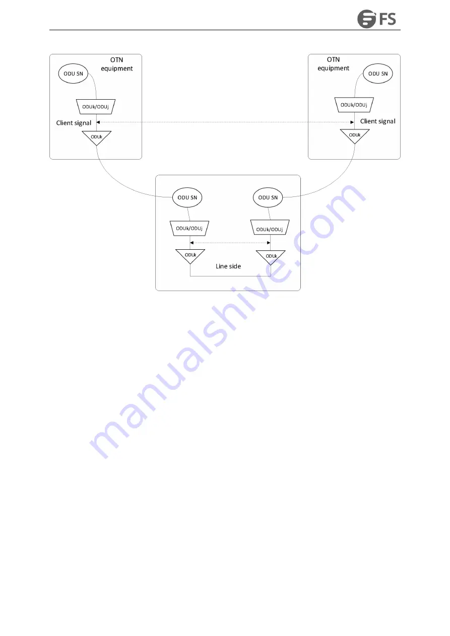
Figure6-20 Schematic Diagram of SM Overhead Configuration
The line side NE of the two ends is OTU2 service (configured according to the service type of the client side).
Enable the monitoring function of SM overhead on the OTU2 layer at both ends, and then set the values of
sending TTI and expected TTI. For detailed configuration, please see the detailed steps described in 6.2.1. If the
values of sending TTI and receiving TTI at both ends conform to the overhead establishment rules listed in Table
6-1, then the line Configuration is correct and the service can be received and dispatched normally.
According to the PM overhead configuration rules described in 6.2.2, the PM overhead is planned as follows:
Содержание M6500 Series
Страница 12: ...M6500 Series NE Configuration Manual 11 Figure 1 3 Start NMS Server...
Страница 63: ...M6500 Series NE Configuration Manual 62 Figure 4 34 Parameter Reading of WDM CFP2 Optical Transceiver...
Страница 105: ...M6500 Series NE Configuration Manual 104 Figure5 80 Site to Site Primary and Standby Protection Environment...
Страница 109: ...M6500 Series NE Configuration Manual 108 Figure6 5 TP Multiplexing Configuration Step 2...
Страница 113: ...M6500 Series NE Configuration Manual 112 Figure6 12 Set Line Side PM Overhead...
Страница 116: ...M6500 Series NE Configuration Manual 115 Figure6 16 Configure Line Side Port TTI...
Страница 117: ...M6500 Series NE Configuration Manual 116 Figure6 17 Configure Client Side Local End Port TTI...
Страница 118: ...M6500 Series NE Configuration Manual 117 Figure6 18 Configure Client Side Opposite End Port TTI...
Страница 129: ...M6500 Series NE Configuration Manual 128 Figure7 10 Select Protection Mode...
Страница 138: ...M6500 Series NE Configuration Manual 137 Figure8 14 Alarm Details Figure8 15 Alarm Document Link...


