ELECTRICAL TESTS AND SERVICE PROCEDURES
Page 41
Service Manual TDR8 P Gas form 9124023 rev. 01/2022
WARNING:
Disconnect the electrical power to the machine
at the main circuit box. Place a tag on the circuit box indica-
ting the circuit is being serviced.
ELECTRICAL TESTS AND SERVICE PROCEDURES
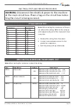
Temperature
Resistance Ω
°F
°C
± 5 Ohms
32
0
1000
60
16
1062
70
21
1082
80
27
1106
90
32
1124
100
38
1148
125
52
1202
150
65
1252
200
94
1362
250
121
1464
350
177
1674
450
233
1880
Note:
When testing the resistance of the sen-
sor remove the wiring. Refer to the removal
and replacement part of the manual on how
to do this.
1. Remove the wiring from the sensor.
2. Connect a temperature sensor to the
probe for comparison.
3. Test the probe with an Ohmmeter.
PT1000 SENSOR TEST
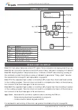
DRIVE MOTOR, BLOWER AND TRANSFORMER TEST
Type
Description
Voltage
Resistance Ω
TDR 8
Drive motor
230
Between white A and white wire ~ 234
Between white A and brown wire ~ 117
Between white and brown wire ~ 117
TDR 8
Blower rotisserie
230
Between blue and brown wire ~ 310
Between blue and black wire ~ 190
Between brown and black wire ~ 500
TDR 8
Transformer
230/12
Between white and white wire ~9
Between white and other colors infinite
Between yellow and red wire ~0,5
Between grey and blue wire ~0,5
Between yellow and grey infinite
Between yellow and blue wire infinite
Between grey and red wire infinite
Between red and blue wire infinite
Note:
When testing the resistance remove the wiring.

