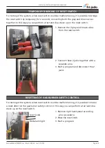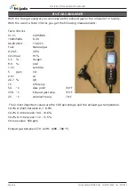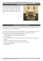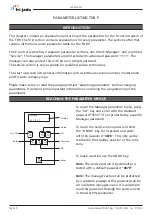
A
B
C
C A
B
REMOVAL AND REPLACEMENT OF PARTS
Page 35
Service Manual TDR8 P Gas form 9124023 rev. 01/2022
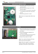
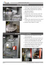
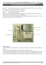
1. Remove the right side panel and the gas
burner safety control according prior pro-
cedures.
2. Remove the nuts from the pipe clamps to
create some clearance.
3. Remove the 4 screws on the top and
bottom flange from the gas control block.
4. Remove the wiring.
5. Reverse the procedure to install.
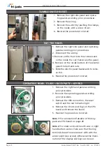
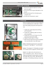
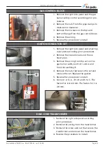
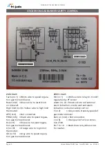
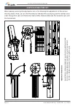
1. Remove the right side panel and small top
cover plate according prior procedures.
2. Remove the insulation around the ex-
haust pipe.
3. Remove the wiring from the set on the
gas burner safety control C and A and
from the earthing B.
4. Remove the nuts that secure the set and
remove the set. Replace the gasket.
5. Reverse the procedure to install.
6. Connect A to A , B to B and C to C. The
faston for A is 4.8 mm. The faston for C is
2.8 mm.
GAS CONTROL BLOCK
IGNITION/IONIZATION SET
RING CORE TRANSFORMER
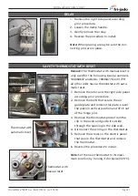
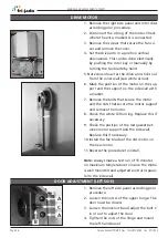
1. Remove the right side panel according
prior procedure.
2. Remove the wiring from the transformer.
3. Remove the screw and nut that secure the
transformer and remove the transformer.
4. Reverse the procedure to install.

