WORKING OF THE GAS FIRED ROTISSERIE
Page 40
Service Manual TDR8 P Gas form 9124023 rev. 01/2022
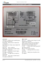
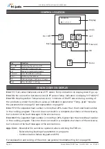
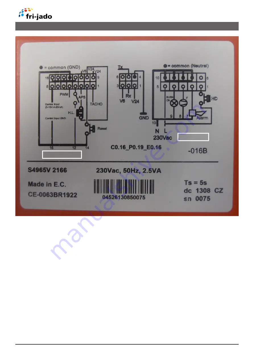
STICKER ON GAS BURNER SAFETY CONTROL
230 V circuit:
HD (nr. 1) = White wire to relay K1. On/off
regulation by PT sensor
Alarm (nr. 2) = Brown wire to red external
alarm indication on side wall and alarm
indication on burner safety control.
F (nr.3)
= Grey wire to stand-by speed of
gas mixture blower.
Burn on (nr.4) = Not connected.
L (nr.5)
= Orange wire for live connec-
tion 230V.
Nr. 7 to 10 = Black-blue- red-yellow wires
for neutral.
230V circuit
24V DC circuit
24V circuit:
Tacho (nr.1) = White wire to speed regula-
tion gas mixture blower.
Reset (nr.2) = Brown wire to reset knob
on side wall.
High limit (nr.3) = Yellow wire to high limit
thermostat.
APS (nr.4)
= Not connected.
PWM (nr.5) = Black wire to speed regula-
tion gas mixture blower.
BL (nr.9)
= Blue wire to speed regula-
tion gas mixture blower.
O (nr.10)
= Orange wire to high limit
thermostat.
GR (nr.13) = Grey wire to speed regula-
tion gas mixture blower.

