


Page 22
Service Manual STG5/7 intelligent STW5/7 intelligent form 9123999 rev. 05/2010
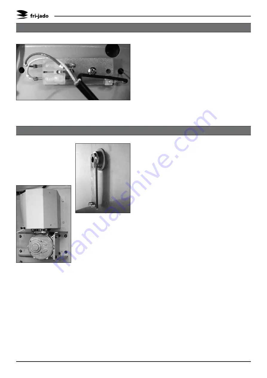
REMOVAL AND REPLACEMENT OF PARTS STG
Remove the right side panel according to
1.
prior procedure.
Disconnect the wiring of the sensor.
2.
Remove the screw that secures the sensor
3.
and remove the sensor.
Reverse the procedure to install.
4.
Note:
The wiring cable is an insulated cable
with an earthing screen.
PT1000 SENSOR
Remove the right side panel and rotor
1.
discs according to prior procedure.
Disconnect the wiring of the motor. Check
2.
where the wire, marked A is connected.
Remove the screws that secure the fan
3.
cover and remove the cover.
(STG 5 only) Remove the nuts that secure
4.
the motor and remove the motor.
(STG 7 only) Set the drive arm in a posi-
5.
tion vertical downwards. This can be done
manually or by turning the fan blade by
hand.
Mark the position of the motor support
6.
with a marker.
Remove the bolts that secure the motor
7.
and the nuts that secure the motor sup-
port and remove the motor.
Check the white Teflon ring. Replace if
8.
necessary.
Install the fan blade on the new motor.
9.
Reverse the procedure to install.
10.
Note:
Always make a test run on maximum
temperature to insure the motor is well
mounted and adjusted.
DRIVE MOTOR