


Flash Memory Array and Control
Freescale Semiconductor
12-9
PXR40 Microcontroller Reference Manual, Rev. 1
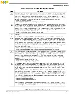
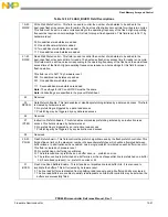
17
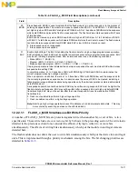
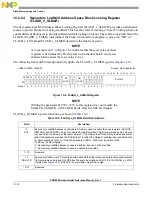
RWE
Read While Write Event Error. RWE provides information on previous RWW reads. If a Read While Write
error occurs, this bit is set to 1. This bit must then be cleared, or a reset must occur before this bit returns
to a 0 state. This bit may not be written to a 1 by the user. If RWE is not set, or remains 0, this indicates
that all previous RWW reads (from the last reset, or clearing of RWE) are correct. Since this bit is an error
flag, it must be cleared to a 0 by writing a 1 to the register location. A write of 0 has no effect.
0 Reads are occurring normally.
1 A Read While Write Error occurred during a previous read.
18
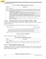
SBC
Single Bit Correction. SBC provides information on previous reads provided the FLASH_x_UT0[SPCE] is
set. If a single bit correction occurred, the SBC bit is set to a 1. This bit must then be cleared, or a reset
must occur before this bit returns to a 0 state. If SBC is not set, or remains 0, this indicates that all previous
reads (from the last reset, or clearing of SBC) did not require a correction. Since this bit is an error flag,
it must be cleared to a 0 by writing a 1 to the register location. A write of 0 has no effect.
0 Reads are occurring without corrections.
1 A Single Bit Correction occurred during a previous read.
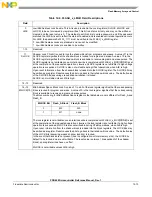
19
Reserved
20
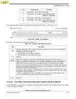
PEAS
Program/Erase Access Space. PEAS is used to indicate which space is valid for program and erase
operations, either main array space or shadow space. PEAS = 0 indicates that the main address space is
active for all FC program and erase operations. PEAS = 1 indicates the shadow address space is active
for program/erase. The value in PEAS is captured and held when the shadow block is enabled with the
first interlock write done for program or erase operations. The value of PEAS is retained between sampling
events (i.e. subsequent first interlock writes). The value in PEAS may be changed during
erase-suspended program, and reverts back to its’ original state once the erase-suspended program is
completed. PEAS is read only.
0 Shadow address space is disabled for program/erase and main address space enabled.
1 Shadow address space is enabled for program/erase and main address space disabled.
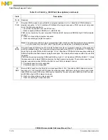
21
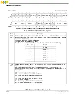
DONE
State Machine Status. DONE indicates if the flash module is performing a high voltage operation. DONE
is set to a 1 on termination of the flash module reset. DONE is read only. DONE is cleared within Tdone
of a 0 to 1 transition of EHV which initiates a high voltage operation. DONE is cleared within Tres of
resuming a suspended operation. DONE is set to a 1 at the end of program and erase high voltage
sequences. DONE is set to a 1 within Tdones of a 1 to 0 transition of EHV which aborts a high voltage
operation.
0 Flash is executing a high voltage operation.
1 Flash is not executing a high voltage operation.
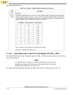
22
PEG
Program/Erase Good. The PEG bit indicates the completion status of the last flash program or erase
sequence for which high voltage operations were initiated. The value of PEG is updated automatically
during the program and erase high voltage operations. Aborting a program/erase high voltage operation
causes PEG to be cleared, indicating the sequence failed. PEG is set to a 1 when the module is reset.
PEG is read only.
The value of PEG is valid only when PGM = 1 and/or ERS = 1 and after DONE transitions from 0 to 1 due
to an abort or the completion of a program/erase operation. PEG is valid until PGM/ERS makes a 1 to 0
transition or EHV makes a 0 to 1 transition. The value in PEG is not valid after a 0 to 1 transition of DONE
caused by PSUS or ESUS being set to logic 1. If PGM and ERS are both 1 when DONE makes a qualifying
0 to 1 transition the value of PEG indicates the completion status of the PGM sequence. This happens in
an erase-suspended program operation.
0 Program or erase operation failed.
1 Program or erase operation successful.
Note: If program or erases are attempted on blocks that are locked, the response from flash is PEG = 1,
indicating that the operation was successful, and the contents of the block are properly protected
from the program or erase operation.
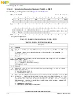
Table 12-4. FLASH_x_MCR Field Descriptions (continued)
Field
Description
Содержание PXR4030
Страница 1: ...PXR40 Microcontroller Reference Manual Devices Supported PXR4030 PXR4040 PXR40RM Rev 1 06 2011...
Страница 30: ...PXR40 Microcontroller Reference Manual Rev 1 Freescale Semiconductor xxx...
Страница 40: ...PXR40 Microcontroller Reference Manual Rev 1 xl Freescale Semiconductor...
Страница 66: ...Memory Map PXR40 Microcontroller Reference Manual Rev 1 2 4 Freescale Semiconductor...
Страница 120: ...Signal Descriptions 3 54 Freescale Semiconductor PXR40 Microcontroller Reference Manual Rev 1...
Страница 158: ...Power Management Controller PMC 5 26 Freescale Semiconductor PXR40 Microcontroller Reference Manual Rev 1...
Страница 182: ...Frequency Modulated Phase Locked Loop FMPLL 6 24 Freescale Semiconductor PXR40 Microcontroller Reference Manual Rev 1...
Страница 278: ...System Integration Unit SIU 7 96 Freescale Semiconductor PXR40 Microcontroller Reference Manual Rev 1...
Страница 280: ...System Information Module PXR40 Microcontroller Reference Manual Rev 1 8 2 Freescale Semiconductor...
Страница 300: ...Boot Assist Module BAM 9 20 Freescale Semiconductor PXR40 Microcontroller Reference Manual Rev 1...
Страница 346: ...Interrupts and Interrupt Controller INTC 10 46 Freescale Semiconductor PXR40 Microcontroller Reference Manual Rev 1...
Страница 352: ...General Purpose Static RAM SRAM 11 6 Freescale Semiconductor PXR40 Microcontroller Reference Manual Rev 1...
Страница 432: ...Core e200z7 Overview PXR40 Microcontroller Reference Manual Rev 1 13 44 Freescale Semiconductor...
Страница 460: ...Peripheral Bridge PBRIDGE 15 16 Freescale Semiconductor PXR40 Microcontroller Reference Manual Rev 1...
Страница 478: ...Memory Protection Unit MPU 16 18 Freescale Semiconductor PXR40 Microcontroller Reference Manual Rev 1...
Страница 496: ...Error Correction Status Module ECSM 17 18 Freescale Semiconductor PXR40 Microcontroller Reference Manual Rev 1...
Страница 524: ...Periodic Interrupt Timer PIT_RTI 20 12 Freescale Semiconductor PXR40 Microcontroller Reference Manual Rev 1...
Страница 740: ...FlexRay Communication Controller FLEXRAY 22 156 Freescale Semiconductor PXR40 Microcontroller Reference Manual Rev 1...
Страница 860: ...FlexCAN Module 24 50 Freescale Semiconductor PXR40 Microcontroller Reference Manual Rev 1...
Страница 928: ...Deserial Serial Peripheral Interface DSPI 25 68 Freescale Semiconductor PXR40 Microcontroller Reference Manual Rev 1...
Страница 982: ...Enhanced Serial Communication Interface eSCI 26 54 Freescale Semiconductor PXR40 Microcontroller Reference Manual Rev 1...
Страница 1114: ...Enhanced Queued Analog to Digital Converter EQADC 27 132 Freescale Semiconductor PXR40 Microcontroller Reference Manual Rev 1...
Страница 1167: ...Decimation Filter Freescale Semiconductor 28 53 PXR40 Microcontroller Reference Manual Rev 1...
Страница 1168: ...Decimation Filter 28 54 Freescale Semiconductor PXR40 Microcontroller Reference Manual Rev 1...
Страница 1262: ...Enhanced Time Processing Unit eTPU2 29 94 Freescale Semiconductor PXR40 Microcontroller Reference Manual Rev 1...
Страница 1399: ...Nexus Development Interface NDI Freescale Semiconductor 31 83 PXR40 Microcontroller Reference Manual Rev 1...
Страница 1400: ...Nexus Development Interface NDI 31 84 Freescale Semiconductor PXR40 Microcontroller Reference Manual Rev 1...


