Operating Manual CMGZ 622
22
9.3
Setup the PID Controller
The setup of the PID controller section depends on the operating mode of your
application. Thus refer to „10. Setup of an Unwind Brake Controller“ / „11. Setup of
an Unwind Drive Controller“ / „12. Setup of a Winding Drive Controller“ / „13. Setup
of a Line Drive Controller“. The instructions in the following sections assume you
have already done the specific settings for the operating mode of your application.
9.4
Entering the Reference Value
The tension reference value can be inputted by the operating panel or interface, or by
the analogue input:
reference input by operating panel or interface
•
Set parameter
reference internal / external
to
internal
•
Execute special function
Edit ref. value
(ref. to fig. 12). Input new reference value
with
↑
↓
keys and save it with
↵
key.
reference input by analogue input
•
Set parameter
reference internal / external
to
external
•
Apply 0...10V source to the analogue input (ref. to wiring diagram)
•
Set parameter
scale ref. input 1
and
scale ref. input 2
to the required reference
value range (refer to „14. Parametrization“)
•
Set the value of the voltage source according to the required reference value.
9.5
Determination of the control parameters
Experimental determination of the control parameters (recommended)
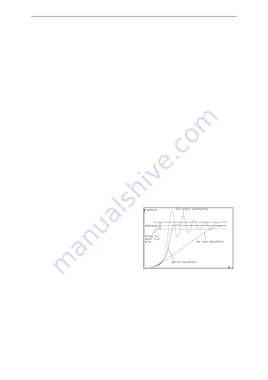
If the behaviour of the control loop is
unknown, tuning is done by means of a
systematic approach (fig. 15):
•
Set parameter
Derivative D
to 0s
(only if PID configuration is used)
•
Set parameter
Integral I
very high
(100.00s)
•
Set parameter
Proportional P
very
small (for ex. 1.00)
•
Enable controller (ref. to
„9.8 Automatic operation“)
•
If control loop is not oscillating:
Increase
Proportional P
•
If control loop is oscillating: decrease
Proportional P
•
Repeat this procedure until the control loop is stable and nearly oscillating. The
controller can remain enabled; the controller parameters may be changed during
automatic operation.
•
If the control loop is running stable with the „P“ component, the
Integral I
can be
decreased until the steady error disappears.
•
If the
Integral I
is too small, the control loop will become unstable again.
•
(Only using PID configuration): Increase
Derivative D
carefully until the controller
is nearly oscillating.
fig
. 15: Transient effect of the control
system
C431013e


