51
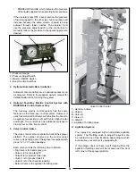
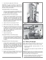
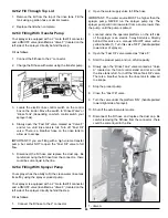
• PRESSURE GAUGE which indicates the pressure
of the liquid supplied to the operating boom sections.
If the operator shuts OFF a boom section, the pressure
of liquid supplied to the other two boom sections will
increase because the same volume of liquid is being
pumped through fewer nozzles. The operator must
use the pressure adjust switch on the control box to
manually reduce the pressure to the operating pressure
desired.
1 - Pressure Gauge
2 - Pressure Adjust Switch
3 - Master ON/OFF Switch
4 - Boom Section Switches
3. Optional Automatic Rate Controller:
Automatic rate controllers are an optional accessory on
all sprayers. Refer to the separate owners manual for
detailed instructions for using the system.
4. Optional Four-Way Electric Control System with
RAVEN Rate Control System Only
:
The four-way electric control system has the same
features as the three-way control system. However, it
uses four motorized ball valves which allow the boom to
be split into four sections: Left, Left Center, Right Center
and Right. The control box has additional switches to
provide four section boom control.
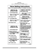
5. Valve Control Center:
The valve control center is located in front of the sprayer
platform. The number of valves on the control center
will vary, depending upon if the sprayer is equipped with
group “A” or “C” option package.
Each valve controls the following (top to bottom):
• Top Valve is for hand spray gun
• Valve A is for rinse tank fill
• Valve B is for product tank rinse
• Valve C is for product tank fill
• Valve D is for the chemical inductor
• Bottom Valve is the agitation throttling valve
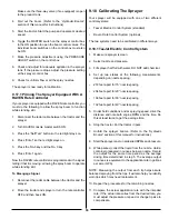
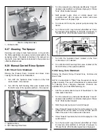
Valve Control Center
1 - Hand Gun Valve
A - Valve A
B - Valve B
C - Valve C
D
-
Valve D
2 - Agitation Throttling Valve
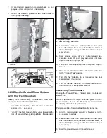
6. Agitation System:
Your sprayer is equipped with an adjustable agitation
system. The throttling valve to adjust the system can
be located in one of two locations, depending on which
accessories your sprayer is equipped with.
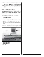
If the sprayer does not have a self cleaning filter, the
agitation throttling valve will be located near the front
left corner of the sprayer platform.
Содержание BW750
Страница 18: ...18...
Страница 19: ...19 Decal A Decal B Decal C Decal D...
Страница 20: ...20 Decal E Decal F Decal G Decal H Decal I Decal J...
Страница 21: ...21 Decal K Decal L...
Страница 36: ...36 9 6 Spray Tip Wear...
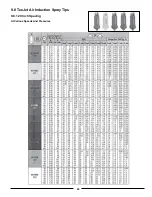
Страница 43: ...43 9 8 TeeJet Air Induction Spray Tips 9 8 1 20 Inch Spacing At Various Speeds And Pressures...
Страница 49: ...49 9 10 TeeJet FloodJet Wide Angle Flat Spray Tips 9 10 1 40 Inch Spacing At Various Speeds And Pressures...
Страница 57: ...57 Instructions Valve Settings For Accessory Kits Refer To The Operator s Manual For Detailed Instructions...
Страница 81: ...81 12 3 Raven Console Calibration Information...
Страница 83: ...83 Notes...


