24
4. Sprayer Setup And Assembly
4.1 Wheel Spacing
Wheel spacing can be adjusted from 62 inches (minimum)
to 80 inches (maximum).
To change wheel spacing proceed as follows:
^
DANGER
Sprayer can fall during wheel spacing
adjustment and crush person working under
sprayer. Death or serious injury will result.
Support the sprayer securely when adjusting
wheel spacing.
1.
Hitch sprayer to tractor (refer to the “Hitching” section
on page 13 of this manual). Place chocks or blocks in
front of and behind wheel on opposite side of wheel to
be adjusted.
2.
Measure and mark center of sprayer frame to assure
equal spacing of wheels from sprayer centerline.
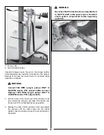
3. Place a hydraulic or screw jack under the sprayer frame
behind the axle on the same side as the wheel to be
adjusted. Jack up the sprayer high enough to raise the
wheel from the ground.
4. Block the sprayer frame to keep sprayer from dropping
if jack should fail or lose pressure.
5.
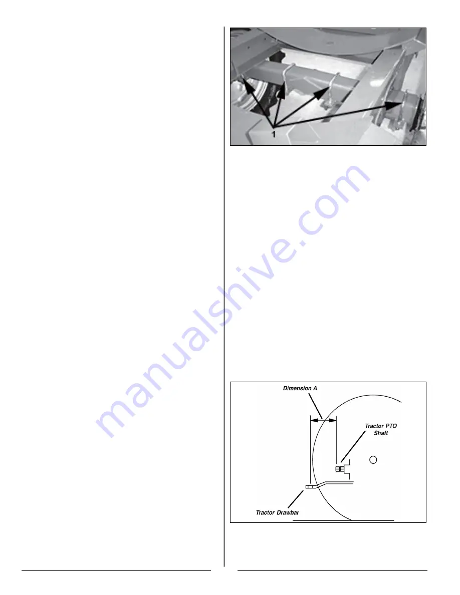
Loosen the nuts on the U-bolts securing the wheel and
hub assembly to the sprayer frame.
6.
Slide the wheel and hub assembly in or out to the desired
distance. Measure from the centerline of the sprayer to
the centerline of the tire. DO NOT exceed the minimum
62 inch or maximum 80 inch distances.
7. Tighten the hex nuts on the U-bolts.
8.
Lower the wheel to the ground.
9. Repeat steps 3 through 8 for the wheel assembly on the
other side of the sprayer.
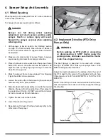
4.2 Implement Driveline (PTO Drive
Pumps Only)
^
WARNING
Before working on PTO shaft or connecting
or disconnecting it, STOP tractor, apply the
parking brake, and make sure that the tractor
motor has stopped turning.
The Fast Sprayer is designed to be used with a tractor
having a 540 RPM PTO unless your sprayer has a 1000
RPM centrifugal pump (Optional).
Adjust the tractor drawbar so the distance from the end of
the PTO shaft to the center of the drawbar hitch pin hole
(Dimension A) is 14.00” for 540 RPM PTO or 16.00” for 1000
RPM PTO.
NOTE: If the hitch pin hole is located well behind the tractor
tires, the operator can make a turn sharp enough to damage
the driveline.
Содержание BW750
Страница 18: ...18...
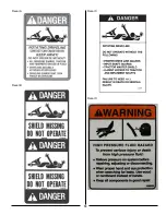
Страница 19: ...19 Decal A Decal B Decal C Decal D...
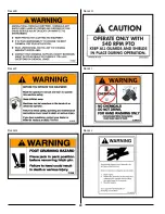
Страница 20: ...20 Decal E Decal F Decal G Decal H Decal I Decal J...
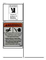
Страница 21: ...21 Decal K Decal L...
Страница 36: ...36 9 6 Spray Tip Wear...
Страница 43: ...43 9 8 TeeJet Air Induction Spray Tips 9 8 1 20 Inch Spacing At Various Speeds And Pressures...
Страница 49: ...49 9 10 TeeJet FloodJet Wide Angle Flat Spray Tips 9 10 1 40 Inch Spacing At Various Speeds And Pressures...
Страница 57: ...57 Instructions Valve Settings For Accessory Kits Refer To The Operator s Manual For Detailed Instructions...
Страница 81: ...81 12 3 Raven Console Calibration Information...
Страница 83: ...83 Notes...

