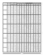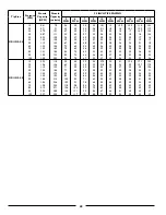
50
9.11 Equipment Matching
To insure the safe and reliable operation of the sprayer, it is
necessary to use a tractor with appropriate specifications.
As a guideline, insure that these requirements are met:
1. Tractor Requirement:
The fully loaded sprayer should be no more than 1.5
times the tractor weight. This insures that the unit
has the required stability and control in hilly terrain and
during transport.
2. Front End Weights:
By following recommendations for tractor power, tractor
will have sufficient weight to provide stability during field
operation or when transporting. It is also recommended
that each tractor be equipped with a full compliment of
suitcase weights on front of tractor. This will provide the
required weight on front for turning and extra traction if
equipped with front wheel assist.
3. Hydraulic System:
Tractor hydraulic system must be capable of 8 gpm (24
lpm) at 2000 psi (13,800 kPa) to operate lift cylinders
and drive motor. Either closed center or open-centered
systems can be used. However an open centered
hydraulic system is limited to 8 gpm maximum.
Note: Contact factory for an optional flow control for use
with high flow open center system.
Two or three remote outlets are required to operate the
sprayer.
1. BW500EF & EFT main lift (single acting, powered up,
gravity down).
BW750/60 (double acting, controls all folding function).
2. BW500EF & EFT, folds wings in or out.
3.
For optional hydraulic drive centrifugal pump.
Note: Always place hydraulic control lever in detent to
provide a constant flow of oil to pump drive motor.
9.12 Sprayer Controls
Sprayer operation and liquid flows are controlled by a
combination of controls on the tractor and the sprayer.
1. Triple Electric Control:
This system consists of three electric ball valves and a
electric pressure regulating valve which are all mounted
on the top of the boom mid section of the sprayer. The
control box is mounted on the tractor.
1 - Electric Ball Valves
2 - Electric Pressure Regulating Valve
Standard Control Box
2. Control Box:
The control box consists of the following components:
• MASTER ON/OFF switch which controls power to
the valves for each boom section. When power is
supplied to the valves, the valves open, allowing
liquid to flow to the boom sections.
NOTE: The toggle switches for the individual boom
sections must be ON to energize the valves.
•
Individual toggle switches which allow the operator
to control flow to the individual boom sections (L,
left; C, center; and R, right). Turning a switch OFF
allows the valve for that section to close.
• PRESSURE ADJUST toggle switch which allows
the operator to INCREASE (+) or DECREASE (-)
the pressure of the liquid supplied to the boom
sections. When the operator releases the switch
after adjusting the pressure, the switch automatically
returns to its center NEUTRAL position.
NOTE: When making adjustments, monitor pressure
carefully. The control system does not have automatic
HIGH or LOW pressure limit switches.
Содержание BW750
Страница 18: ...18...
Страница 19: ...19 Decal A Decal B Decal C Decal D...
Страница 20: ...20 Decal E Decal F Decal G Decal H Decal I Decal J...
Страница 21: ...21 Decal K Decal L...
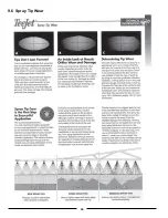
Страница 36: ...36 9 6 Spray Tip Wear...
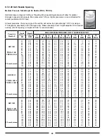
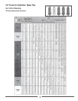
Страница 43: ...43 9 8 TeeJet Air Induction Spray Tips 9 8 1 20 Inch Spacing At Various Speeds And Pressures...
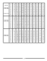
Страница 49: ...49 9 10 TeeJet FloodJet Wide Angle Flat Spray Tips 9 10 1 40 Inch Spacing At Various Speeds And Pressures...
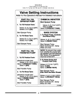
Страница 57: ...57 Instructions Valve Settings For Accessory Kits Refer To The Operator s Manual For Detailed Instructions...
Страница 81: ...81 12 3 Raven Console Calibration Information...
Страница 83: ...83 Notes...

