background image

93

Revision date: 12.02.16

Black-out System Installation

ASSEMBLE AND INSTALL DRIVE PIPE COMPONENTS

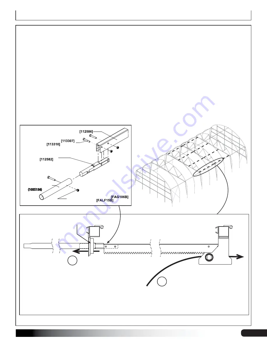
1.  Attach a 112582 rack drive coupler to each end of the four (4) 112586 rack arms using 113307 bolts & 113310 nuts.  


NOTE:

 Square ends of the couplers will sit inside the rack arms as shown below.

2.  At one end of each rack arm, add a 13' section of drive pipe (105S156). Splice the 

plain 

ends of the drive pipe onto 

the rounded, open ends of the 112582 couplers using 1/4"x1-1/2" bolts (FAG106B) and 1/4" lock nuts (FALF15B). 

3.  With assistance, or a lift machine, hoist the rack/pipe assembly into one rack drive, with the teeth of the rack arm 

facing DOWN to marry up with the rack drive gears. Push the rack/pipe assembly through the rack drive until the 
the swaged end of the pipe section is able to be guided through the drive roller on the next rafter (see #1 & #2 in 
diagram below). Position so that the weight of the rack/pipe assembly is fully supported by the rack drive and the 
drive roller. Repeat for each rack drive location. 
 

ATTENTION:

 Depending on greenhouse length, it may be necessary to have to splice the pipe end of this rack/

pipe assembly with the previously installed drive pipe that is sitting loosely on the telescoping purlin. See following 
pages for details.

RACK ARM DRIVEPIPE

COUPLING 

-(2X) M6 X 25MM BOLT 

-(2X) M6 NUT 

RACK ARM 

-(1X) 1/4" X 1-1/2" CAP SCREW 

-(1X) 1/4" LOCKNUT 

1.05" DRIVEPIPE

(105S156)

1

2

Guide the rack/pipe 
assembly up through 
the rack drive until the 
swaged end of the drive 
pipe has cleared the drive 
roller on the next rafter.

112588 

Rack Drive

112586

Rack Arm

105S156

Drive Pipe

CUT-AWAY

SIDE VIEW

112581

Drive Roller

Once the rack/pipe has 
cleared the drive roller, 
pull the swaged end of 
the pipe back through 
the drive roller. Guide 
through until the weight 
of the rack/pipe is evenly 
supported by the drive 
roller and the rack drive.

Содержание Growers Supply GrowSpan 500 Series

Страница 1: ...Revision date 12 02 16 2016 Growers Supply All Rights Reserved Reproduction is prohibited without permission Series 500 Greenhouse Kit w Blackout System 30 Wide Series 500 Greenhouse Kit w Blackout System ...

Страница 2: ... The anchoring methods shown in this manual for buildings with mounting feet or buildings with ground posts are temporary in nature For the recommended permanent anchoring methods consult the MUST READ documents that also shipped with your building The diagrams presented in that guide show anchoring methods designed to meet typical loads and forces Consult that document and read its contents befor...

Страница 3: ... ventilation if the structure is enclosed Do not store hazardous materials in the structure Provide proper ingress and egress to prevent entrapment NEVER hang items from the system components LOCATION Choosing the proper location is an important step before you begin The following suggestions and precautions will help determine whether your selected location is best Always check local building cod...

Страница 4: ... columns to the site Concrete is not supplied and can be purchased locally 12 Install all blackout shade system end header hardware 13 Install end wall cladding 14 Attach the 104546 to the end rafters 15 Install main cover 16 Install blackout shade system components 17 Complete and return all warranty information as instructed if present REQUIRED TOOLS The following list identifies the main tools ...

Страница 5: ...fter legs ground posts Actual frame shown in the examples above may differ These are presented for illustration purposes only Ground Level Inside of Shelter Outside of Shelter Secure baseboard and ribbon board joints between rafters as shown for best results RIBBON BOARD FOR ROLL UP SIDES OPTIONAL In some instances a ribbon board is installed along the side of the frame This is optional for buildi...

Страница 6: ...urnbuckle FA4470B FA4482B and FA4484B Tek Screw 100441 100442 and 100443 Magnetic Nut Setter AS1084 3 16 Cable Thimble 113236Z147 Aluminum H Channel 104213 Aluminum U Profile 102197 Spring Channel 102198 Spring Wire The following graphics will help identify the basic parts of the frame Some parts are not shown 115249 End Rafter Mounting Feet Only 115250 Mid Rafter Mounting Feet Only ...

Страница 7: ...eading Edge 113316 Cloth Fastener Clip 113314 Upper Wire Guide 112571 Rack Drive Coupler 112588 Rack Drive 112608 Aluminum Clamp 115177 Drive Pipe Clamp 113315 Wire Snap Clip 112567 Cloth Weight QH1330 Bracket 104548 End Cap 111983 Foam Tape 115359 Motor Support Bracket 104774 Polycarb Tape 111984 Keder Channel 115018Z046 Keder Sealing Strip 115198 Black Out Tape 113323 Monofilament Clip ...

Страница 8: ...g instructions for system framing RQVXOW WKH 0RWRU DUH DQG 0DLQWHQDQFH VHFWLRQ DW WKH HQG RI WKHVH LQVWUXFWLRQV IRU DOO PRWRU GULYH VKDIW RSHUDWLRQ SURFHGXUHV 7KRXJK WKH GLDJUDPV PD QRW EH VSHFLILF to the system frame being assembled all DSSOLFDWLRQV DUH WKH VDPH GMXVW DFFRUGLQJO ELECTRICAL WARNING The vent frames are metal and will conduct electricity Exercise caution if working around or on the ...

Страница 9: ...illustration below to identify main parts 1 Prepare site and set the ground posts mounting feet in or on concrete 2 Locate the required parts for each assembly procedure 3 Assemble the rafters and main frame Ground Level FRONT End Wall Column End Rafter Interior Rafter Webbing Strut End Wall Header End Wall Cross Beam Ridge Purlin Side Purlin Rafter Support Chord Vertical Header Cable Ground Post ...

Страница 10: ... site and anchor the feet to the site before assembling the frame Read the following information and use the diagram to layout the position of your building Once the string lines are set to mark the location continue with the Mounting Feet section Unless you are securing feet to concrete piers do not dig holes if your building is equipped with rafter mounting feet Read the information on the Mount...

Страница 11: ...ms Complete these steps 1 Stake the outline of the building using string line and batter boards Set batter boards 3 back from the building corners Check to ensure that the building layout is square Cover or panels if equipped will not install properly if the building frame is not square once assembled 2 Consult the diagrams in the Quick Start section to verify the frame length and width dimensions...

Страница 12: ...toward the ground 2 With assistance brace all posts in place See diagram below All posts to be plumb before adding concrete Use the baseboard mounting holes and customer supplied fasteners and stakes to hold posts in place 3 Add concrete to anchor posts in holes Fill hole so concrete remains below the finished grade 6WDNH URXQG 3RVWV IRU RQFUHWH Finished Grade Set all posts at the same height Addi...

Страница 13: ...eter is 12 Set all ground posts 24 below finished grade Consult local building codes and qualified contractors for additional details when digging the post holes and setting the ground posts Follow established codes and construction practices Optional Before setting the posts drill a hole through the bottom of each ground post 2 3 from the end and insert a 6 8 length of rebar through it This will ...

Страница 14: ...teps 1 Determine on center position of base plate Mark center of plate and mark on center position of plate on foundation Consult layout in technical documents 2 Square plate on foundation align marks and mark bolt hole locations using base as a template 3 Remove base plate and drill mounting holes according to requirements of anchor bolts 4 Clean bolt holes according to anchor bolt specifications...

Страница 15: ...ents at the end of these instructions before and during the rafter assembly process for details Assistance is required to assemble the rafters and frame Assemble all main sections of rafters as described below and set aside STEP 1 Select the rafter pipes to assemble one rafter STEP 3 Secure each rafter joint using two 2 FA4482B Tek screws STEP 2 Slide the separate pipe pieces together STEP 4 Wrap ...

Страница 16: ...ord components and install web strut components 8 Return to each band clamp and secure each clamp to the rafter using a Tek screw Install Tek screw in a position that will not contact the cover or shade panels when they are installed See next page RAFTER ASSEMBLY Support Chords Support chord assemblies act as the horizontal surface to which black out panels are attached and against which the black...

Страница 17: ... 3 8 X 1 HEX BOLT 1x 3 8 LOCK WASHER 2 SQ TUBE INSERT 115187 CROSS BEAM CROSS BEAM 4x 3 8 X 3 HEX BOLT 4x 3 8 WASHER 4x 3 8 LOCK WASHER 4x 3 8 HEX NUT DETAIL A DETAIL B DETAIL D DETAIL C WEB ST08475D13G17S1 BAND CLAMP 106735 BAND CLAMP 106735 BAND CLAMP 106735 BAND CLAMP 103856 BAND CLAMP 103856 BAND CLAMP 103856 BAND CLAMP 103856 WEB ST08475D13G17S1 WEB ST05050D13G17S1 WEB ST05050D13G17S1 CHORD T...

Страница 18: ...ers Jig sets the on center spacing of rafters Examine the photo below and use it to build a jig to space rafters during purlin installation Use 2 x 4 lumber and wood fasteners Customer supplied rafter spacing jig Finished Grade 2 103856 Clamps 2 103856 Clamps 2 103856 Clamps 2 103856 Clamps Rope or Cable Slide two 103856 band clamps over each of the first two ground posts base plates at each end o...

Страница 19: ...fter chord support components Center the ridge purlin on top of the rafters Secure using the QH1070 and FA4482 Tek screws Install one Tek screw through the side of the strap and into the purlin pipe Finished Grade Approximately 11 Secure side purlins at 11 above the finished grade Secure purlin using QH1070 pipe straps at each end rafter Use 102546 cross connectors at each mid rafter position ...

Страница 20: ...s for connection details After the first few rafters are set and connected by purlins remove the end rafter bracing and continue with the frame assembly 5 0 66 0 FRQWLQXHG IMPORTANT Secure each QH1070 pipe strap to the purlin pipe using one Tek screw Secure all 102546 cross connectors to the rafter and to the purlin pipe using Tek screws Secure all purlin pipe splices using two Tek screws See phot...

Страница 21: ...on for additional information Ridge purlin is installed on top of the rafters unless noted Secure all 102546 cross connectors to the rafter and to the purlin pipe using Tek screws Secure each purlin pipe splice using two Tek screws FA4482B Tek Screws 102546 Cross Connector Purlin Mid Rafter Between End Rafters Purlin Pipe 2 End of Purlin Pipe 2 inside 1 Purlin Pipe 1 Purlin Pipe Splice HELPFUL HIN...

Страница 22: ...22 Revision date 12 02 16 Frame Assembly 5 0 66 0 FRQWLQXHG Customer supplied rafter spacing jig ...

Страница 23: ...Assembly 5 0 66 0 FRQWLQXHG Full Frame with Rafter Chord Support components removed for clarity Full Frame ATTENTION Example shows a 48 frame length Actual frame may differ CABLE ASSEMBLY AND INSTALLATION IS SHOWN IN A LATER PROCEDURE ...

Страница 24: ...arriage bolts and nuts Countersink bolt heads if carriage bolts are not used Continue adding baseboards to complete the first run Splices are made between posts as shown in the drawing below Use a short section of baseboard to secure separate baseboards at a splice See diagram below Repeat steps to install the second run of baseboard on the remaining side of the frame NOTE The boards should be at ...

Страница 25: ...before tightening the cable turnbuckles See photos on the next page Dashed lines indicate cable assembly locations NOTE Purchased shelter will have an even number of bays Upper mid cables can be installed in either of the two center bays 3 104189 Turnbuckle MID Cables SEE BELOW FOR CABLE ASSEMBLY CALL OUT MID Cables CORNER Cables CORNER Cables CORNER Cables CORNER Cables Cable Assembly CORNER CAB2...

Страница 26: ...ackles Secure all band clamps to the rafter pipe using one Tek screw for each band clamp Secure band clamp to pipe Using the diagrams and photos on this and the previous page install all cable assemblies PGBRKAAS01 bracket and AS2167 shackle PGBRKAAS01 bracket and 104189 turnbuckle 104189 turnbuckle and thimble of cable assembly ...

Страница 27: ...wing procedure describes one way to install the ribbon boards 1 Mark ribbon board height along the outside of the frame from end to end using a chalk line Consult the diagram 2 Align board with outer edge of end rafter and attach to the frame Fastener heads must be flush with board surface Countersink if needed ATTENTION Consult the photos on the next page for additional details 3 Continue adding ...

Страница 28: ... baseboard on a sample frame Photos above show ribbon board attached to the side of an assembled frame Example shows using 2 Tek screws additional purchase to secure board to rafters Screw heads are countersunk below board surface to allow for the installation of the 111613Z144 Customer supplied exterior grade carriage bolts are also an option for fasteners Ribbon Board Baseboard ...

Страница 29: ...s not installed attach the 111613Z144 directly to the rafters using two 2 FA4482B Tek screws at each rafter position See photo Installation without Optional Ribbon Board Splice Piece used for backer to join two separate sections Do not secure two separate sections to the same rafter Splice sections between rafters and use a small piece or other material as a backer Secure using Tek screws as shown...

Страница 30: ...sealing components and drive components are all attached to the mid rafter headers horizontal and vertical ASSEMBLE AND INSTALL MID RAFTER VERTICAL HEADERS Install provided vertical header tubing as shown as every rafter with a support chord assembly S20P100G14SGB vertical header tube FAG355B bolt FAMA38B lock washer FAG363B bolt FAMA38B lock washer 115182 Vertical Header Bracket Rafter Leg Ground...

Страница 31: ...f the ridge vent only Use the cables to square the vent frame on the building frame Tighten until cables are snug Consult the ridge vent technical documents for additional cable installation details Photo shows a sample building with an installed ridge vent in the open position IMPORTANT When attaching the slam rail to the end rafters do not install where vent opening is located See dashed line ab...

Страница 32: ...Splice S125P006 Vent Bearing Plate 111674 Ridge Vent Bottom Rail ATTENTION Vent racks are either curved or straight depending on the application A curved vent rack is shown in this example It may differ from the actual vent rack sent with your vent package Secure bearing plates to the rafters using FA4482B Tek screws Secure bottom rail splices using FA4482B Tek screws ...

Страница 33: ...the curved ridge vent arm at each end of the assembled vent frame Cut to length as needed Drive screws through the u channel and flashing and into the vent frame bow Space Tek screws evenly at 12 on center ATTENTION Photos below show the installation of the u channel If you vent includes the 112390 flashing review the diagrams on the next page before you attach the u channel Install flashing betwe...

Страница 34: ...34 Revision date 12 02 16 Install Ridge Vent Diagram shows flashing and u channel attached to the top of one end bow of vent frame 167 5 9 17 FRQWLQXHG 112390 Flashing 102197 U Channel ...

Страница 35: ...otos near the end of this guide Roof vent slam rail as attached to the top of the rafters Attach using two FA4482B Tek screws at each rafter Vent Drive Axle Slam Rail Roof Vent Bottom Rail 111679 Vent Rack Drive 102197 U Channel and 112390 Flashing installed at each end of the vent Curved Ridge Vent Arm Underside of 112390 Flashing Drive axle for vent constructed out of 1 315 diameter pipe Secure ...

Страница 36: ...Z144 for the vent runs the length of the vent frame and is attached to the tops of the rafters Rail is installed after main vent frame is assembled 115079 Mounting Plate 115093 Motor Slam Rail Slam Rail 9LHZ RI YHQW GULYH DV VHHQ ORRNLQJ XS standing inside the assembled building 115079 Mounting Plate Photo shows vent motor installed with the vent drive shaft attached ATTENTION Photo to the right d...

Страница 37: ...h rafter for conflicts between frame components Adjust as needed 3 Mark the position of the bottom rail on each rafter for reference 4 Locate all of the slam rail sections 111613Z144 needed to create a rail as long as the building 5 Using the marks on the rafters as guides attach the slam rail sections 111613Z144 to the top of the rafters using two FA4482B Tek screws at each rafter Measure and cut...

Страница 38: ... crank handle Vent should open freely and smoothly 7 Close the vent and read the care and maintenance information on the next pate 8 Return to the main building assembly guide and continue as instructed 167 9 17 5 8 2 76 Install U Bolts and Tighten Vent Rack Drive Vent rack u bolts prevent the vent from opening too far and tracking out of the vent rack drives After the ridge vent is assembled and ...

Страница 39: ...st as needed to position and plumb 4 After the vertical supports are in position plumb and the correct distances apart secure the vertical supports in the ground holes with customer supplied concrete Concrete should remain at least 2 4 below the finished grade level so that it does not interfere with construction and the installation of other end frame components doors or end cladding BASE PLATES ...

Страница 40: ... GROUND POSTS NOTE Diagram shows both base plate and ground post options for illustration purposes only Purchased greenhouse will either have all base plates or all ground posts Adjust accordingly Continue with the installation of the end wall header and cross bracing on the following page End Frame Assembly DETAIL A DETAIL B DETAIL C DETAIL A DETAIL B DETAIL C QH1330 FRONT END DOOR END ...

Страница 41: ... 5 x1 5 End Wall Cross Brace 1 5 x1 5 End Wall Cross Brace Header Bracket 111818 Tek screws Tek screws QH1330 U Bracket 115181 3 8 x 3 1 2 bolt FAG365B 3 8 x 3 bolt FAG363B 3 8 x 1 bolt FAG355B 3 8 x 1 bolt FAG355B 3 8 lock washer FAMA38B 3 8 lock washer FAMA38B 3 8 lock washer FAMA38B 3 8 lock washer FAMA38B 3 8 nut FALB04B S15P045 S15P117 S15P117 S20P118 S20P046 S20P05343G14SGC S20P05343G14SGC S...

Страница 42: ...r provided door Dashed lines in below diagram show recommended location of a door If installing in an end wall with ground post mounting dig an 8 10 diameter hole at door column locations at a depth that is below geographic frost line Minimum depth 24 IMPORTANT Consider the door position when open WR SUHYHQW FRQÀLFWV ZKHQ LQVWDOOLQJ DFFHVVRULHV 2 Consult door opening locations and dimensions Cut 1...

Страница 43: ...s Adjust as needed to position and plumb 4 After the vertical supports are in position plumb and the correct distances apart secure the vertical supports in the ground holes with customer supplied concrete Concrete should remain at least 2 4 below the finished grade level so that it does not interfere with construction and the installation of other end frame components doors or end cladding BASE P...

Страница 44: ... GROUND POSTS NOTE Diagram shows both base plate and ground post options for illustration purposes only Purchased greenhouse will either have all base plates or all ground posts Adjust accordingly Continue with the installation of the end wall header and cross bracing on the following page DETAIL A DETAIL B DETAIL C DETAIL A DETAIL B DETAIL C QH1330 End Frame Assembly BACK END PLAIN END ...

Страница 45: ...111818 Tek screws Tek screws QH1330 U Bracket 115181 3 8 x 3 1 2 bolt FAG365B 3 8 x 3 bolt FAG363B 3 8 x 1 bolt FAG355B 3 8 x 1 bolt FAG355B 3 8 lock washer FAMA38B 3 8 lock washer FAMA38B 3 8 lock washer FAMA38B 3 8 lock washer FAMA38B 3 8 nut FALB04B S15P069 S15P069 S15P069 S20P070 S20P070 S20P05343G14SGC S20P05343G14SGC S20P070 S15P069 Ground Level DETAIL A DETAIL B DETAIL C DETAIL D DETAIL E D...

Страница 46: ...or right as needed to avoid obstructions such as end wall columns mid rafter webbing etc Spacing is approximate recommendation and not critical however remember to mirror accordingly on the opposite end ATTENTION Dashed boxes above indicate the locations along WKH KHDGHU SUR OH ZKHUH GULYH components will be installed Avoid installing wire tensioners or brackets in these locations Consult page 124...

Страница 47: ...line consists of WZR WHQVLRQHU EUDFNHWV RQH DWWDFKHG 21 7 81 56 DW HDFK end header At one end attach the 112575 brackets in locations shown below using FAG312B bolts FALB01B nuts Repeat for the other end Verify wire tensioners are positioned on the inside edge of the tubes as shown Install Corner Cable Wire Mounts an inch in from the corner to allow for access to crank wire tensioner Corner Cable ...

Страница 48: ...olycarbonate panels Do not stack panels in direct sunlight Allowing the film to remain intact and in direct sunlight will make the film difficult if not impossible to remove During preparation rest the edges of the panels on cardboard or other material to protect them from dirt and damage Do not install panels on a windy or stormy day or when such conditions are expected Consult the polycarbonate ...

Страница 49: ...g the base of the 30 opening as shown below Run a bead of 112263 construction sealant between the ground and the 113301 tubing Cut to fit as needed IMPORTANT Verify that the outside facing plane of the 113301 tubing is FLUSH with the outside facing plane of the endwall columns and base plates See below 3 Line the outside faces of the 2 x2 vertical header with 111983 expanding weather foam tape Ext...

Страница 50: ...e end wall and working outward install both blackout polycarbonate and clear polycarbonate panels as shown Reference the tables below details on the following page and the technical documents towards the end of these instructions 2 Before securing panels to the wall verify panels are square on the frame and in the desired position Attach using Tek screws and neo bonded washers Install the Tek scre...

Страница 51: ... Photo shows an example of end panel excess being removed using a power tool with a round cutting bit A utility knife can also be used Exercise caution ATTENTION Horizontal run of H Channel that splices clear 8MM polycarbonate panels and blackout polycarbonate panels is uninterrupted as shown to the right Cut and splice vertical runs to fit ...

Страница 52: ... to allow bending of the profile The tighter the curve the closer the notches b The distance between the notches is determined by the degree of the bend required to fit the rafter c Bend the 104546 profile at the notches before installing it Photo shows a sample building with an installed ridge vent in the open position Do not install the 104546 here IMPORTANT For the rounded edge of the rafter pr...

Страница 53: ...eed to be taken care of at the customer s discretion A great deal of carefulness craftsmanship and throroughness is required and proper installation will eliminate most potential issues 115198 black tape is included to seal gaps accordingly Other customer supplied light sealing agents can also be used such as opaque foam non clear caulking regular duct tape etc Below are a few example diagrams of ...

Страница 54: ... Cover will be longest on the vent side of the frame Cover that section of the roof first Cover is typically cut to length after it is secured to the first side of the frame WARNING To prevent damage to the cover and to prevent serious personal injury DO NOT attempt to install the main cover on windy or stormy days Install this vent side first NOTE QVWDOODWLRQ SURFHGXUH PD YDU VOLJKWO GHSHQGLQJ RQ...

Страница 55: ...installation and cutting Consult the diagram in the Quick Start section near the end of this guide for the over the top measurement WEAR EYE PROTECTION WHEN INSTALLING SPRING WIRE Film Cover Installation 4 Along the edge clamp self locking duck billed pliers to the cover material and tie ropes or straps to the pliers NOTE The ropes or straps must reach over top of building to the other side Number...

Страница 56: ... photos throughout this section IMPORTANT To prevent damage to the main cover during installation use additional personnel and lifts as needed Photo above shows lift inside building with assistants pulling cover into position Photo above shows straps clamped to the edge of the cover material which is being pulled up to the installed ridge vent Photo below shows the cover pulled into place Cover Pa...

Страница 57: ...wire See dashed line below Allow a few inches of material to extend past the 111613Z144 NOTE Small photo shows spring wire installed in the 111613Z144 Above assistants are shown standing in a lift inside the building securing the cover to the ridge vent frame Step 6 End Panel Cover Panel A Cover Panel B Step 4 Pull cover up to this point Step 5 Secure to edge of vent Step 6 WEAR EYE PROTECTION WHE...

Страница 58: ...g wire and work down the vent frame to the 104546 attached to rafter Continue to secure cover and work down to side 104546 Step 7 End Panel End Rafter Cover Panel B is installed in a later step NOTE Dashed line shows where cover is to be attached to end rafter Arrows show position of the side run of 111613Z144 ...

Страница 59: ...of material to extend below the 111613Z144 if desired This allows something to grip in the event that you need to stretch cover after installation Remainder of panel will be installed on opposite side Panel A Cut and use for Panel B Step 9 Step 9 Top Channel of 11613Z144 Panel A WEAR EYE PROTECTION WHEN INSTALLING SPRING WIRE 8 Move to the other end rafter and attach the cover to that 104546 using...

Страница 60: ...r to the 111613Z144 attached to the frame See dashed line below Work down each end rafter securing cover to the 104546 channel to side run of 111613Z144 Stretch cover and secure to 111613Z144 See dashed line above Trim excess material from installed cover Step 11 Step 10 Step 11 Step 11 Step 10 Photo above shows 102198 spring wire used to secure cover material to the 104546 attached to the end raf...

Страница 61: ...ver film is already installed loosen the outer film layer and then install the deflector bushing through the inside layer of film and into the blower bracket as shown earlier Once the deflector is installed reattach the outer layer of cover film STEP 7 From inside the greenhouse place the blower motor over the bracket studs and secure in place using the supplied nuts Do not to over tighten the nut...

Страница 62: ...reach from the blower motor to the regulator once it is installed Next carefully cut a hole through the end wall film and attach the hose to the air regulator An assistant may be needed to complete this step Simply insert the end cap into the air regulator and rotate to lock in place Film is sandwiched between the air regulator and the end cap STEP 9 From inside the greenhouse connect the free end...

Страница 63: ...lm in all the same channels as the first film 111614Z144 along the ridge vent 104546 along the end rafters and 11614Z144 along the side walls Add a second run of 102198 spring wire over the first Be careful not to damage the first film during the installation and cutting of the second film Test the air inflation system after installing the second film Photo shows pulling the second layer of film o...

Страница 64: ...en it is closed or down It is installed just above the baseboard attached to the frame and ground level Secure the stabilizer bar to each ground post using an FA4482 Tek screw This component is not used when buildings are equipped with the dropdown side option 857 1 67 5 5 167 7 21 Continue with the installation of the roll up side panels ...

Страница 65: ...65 Revision date 12 02 16 Roll Up Side Panel Installation ...

Страница 66: ...he bottom edge of the roll up panel This assembly runs the length of the frame and serves as the center pipe that the roll up panel wraps around when it is opened for ventilation Complete these steps to assemble the roll up side panel conduit 1 Locate sections of pipe 131S147 to assemble the roll up panel conduit 2 Insert the swaged end of each pipe into the plain end of another pipe until conduit...

Страница 67: ...onduit NOTE Twist the conduit in a direction that wraps the panel toward the inside of the frame This allows water to drain off the building and roll up panel 3 Continue to roll the conduit until excess panel material is wound around conduit and lower edge is positioned at the base of frame 4 Temporarily anchor conduit and panel to the frame or ground to prevent the wind from lifting it away from ...

Страница 68: ...ter with the drilled holes in the conduit 2 4 Position the channel along the end rafter where the Twist of the Wrist assembly will be located 5 Secure upper end of the channel by drilling a 3 8 hole through end rafter and attach as shown Lower end of channel will float and is not attached 3 Select the aluminum channel drill a 3 8 hole through the channel approximately 2 from the end and attach a t...

Страница 69: ...ngs on the side of the bracket that has the two holes Install these before installing the double bearing assembles See the figures below 3 For the spacers on the long bolts insert a 5 16 nut over each bolt These nuts are used as spacers only 5 16 Nut 5 16 Nut 4 Slide the Twist of the Wrist mounting plate over the long bolts and secure the plate with two lock nuts Lock Nuts 5 Attach the Twist of th...

Страница 70: ...e frame and stretches between the ribbon board and the baseboard When installed correctly the anti billow rope helps keep the roll up panel in place when it is fully or partially closed Use the diagram as a guide and complete the steps to install the anti billow rope 1 Beginning at one end rafter take two 2 eye screws FA2155 and attach one to the baseboard and one to the ribbon board Align the FA2...

Страница 71: ...ormation identifies at what point during the assembly a particular component is to be installed or attached to the main building frame IMPORTANT There are some procedures that can occur simultaneously depending on available assistants and equipment but there are some procedures that MUST be done in chronological order Before you begin review below step recommendation and all technical documents to...

Страница 72: ...2722 1 2 flat washers 106953 and 1 2 nuts 106977 attach the motor support bracket to the motor mounting plate as shown below 3 Verify nuts bolts are fully tightened and continue with the motor support assembly installation on the following page 1 2 x 3 bolt 112722 1 2 flat washer 106953 1 2 nut 106977 115359 Motor Support Bracket Motor Support Assembly 113299 Motor Mounting Plate ...

Страница 73: ...ebbing clamps and monofilament wire paths Reference page 46 3 Using 3 8 x 3 bolts FAG363B 3 8 lock washers FAME38B 3 8 flat washers FAME08B and 3 8 nuts FALB04B attach the motor support assembly to the underside of the determined power rafter IMPORTANT Orient the motor support plate so that it points towards the end header where the 113694 wire brackets have been installed page 46 Pre drill attach...

Страница 74: ...o chain NOTE After adding one spacer push connecting link through the chain a little to hold spacer in place Then add the second spacer Push connecting link through second spacer until ends of connecting link are visible See arrow above 3 Take connecting chain link and slide it through first chain until ends are flush with link of first chain section 6 Flip the link ends down and over the sprocket...

Страница 75: ...1 Verify that all spacers are in place and that locking clip is secure 9 Place locking clip over the ends of connecting link 12 Repeat these steps to attach the remaining coupling to motor 7 Take outer spacer and place it over the ends of connecting link Inner Spacers 2 Outer Spacer 1 and Locking Clip 1 77 1 283 1 6 72 02725 FRQWLQXHG Black out System Installation ...

Страница 76: ...and stablize motor into motor mounting plate as shown Attach using included bolts HELPFUL HINT Do not fully tighten motor mounting bolts It may be necessary to adjust the motor slightly when installing the drive shaft CONTACT A LICENSED ELECTRICIAN FOR ALL MOTOR WIRING DETAILS Access Panel If electrical wiring is not completed motor can be manually operated with a drill and a 6mm Allen key adaptor...

Страница 77: ...the process 112571 Rack Drive Coupler 112588 Rack Drive LEFT Rack Drive x1 RIGHT Rack Drive x1 Continue on following page for rack drive location details NOTE There may be instances where the couplers tightly fit onto the rack drives and it may be very difficult to install once rack drives have been attached to the rafter chord Test couplers on all rack drives If the couplers are a snug fit and or...

Страница 78: ...nd field drill the attachment holes 3 Using 5 16 x 3 bolts FAG338B 5 16 flat washers FAME07B and 5 16 lock nuts FALF37B attach the rack drives to the underside of the power rafter as shown below DO NOT TIGHTEN AT THIS TIME RIGHT Rack Drive see orientation note CENTER Rack Drives ORIENTATION NOTE View as seen from the end wall with the 113650 wire tensioners looking towards the end wall with the 11...

Страница 79: ...haft pieces into the corresponding rack drives temporarily secure with Tek screws if necessary and then lift and slide the loosely assembled drive shaft components back into the motor couplers from either side ASSISTANCE WILL BE REQUIRED 5 Reattach the rack drives to the power rafter and tighten the lock nuts Do not secure drive shaft to the couplers at this time X X X X X X X X 2 1 2 2 1 2 X X Me...

Страница 80: ... instructions for location details IMPORTANT Orientation of the monofilament clips is critical Use side view diagram to the right to determine orientation of the monofilament wire clips Verify that the faces of the 113323 monofilament wire clips are facing towards the end wall header with the 113694 wire brackets attached Tube clips are pushed into place over the 2 x2 rafter chord and will stay in...

Страница 81: ... If needed snap chalk lines to ensure straight line locations 2 Using M6x100MM bolts 113308 drive pipe clamp spacers 100P001125 and M6 nuts 113310 attach the telescopic purlin clamp 112608 to the end rafter headers in the locations indicated by the arrows below DO NOT TIGHTEN BOLT AT THIS TIME See diagrams for details It is important that telescoping purlin locations mirror the rack drive location...

Страница 82: ...ce to attach the keder channels webbing brackets bolt heads threads etc A certain high level of craftsmanship will need to be exercised to attach over top these obstructions Notch around obstructions as best as possible See below 2 Where the horizontal header meets the vertical header cut keder channel to fit leaving 1 to 2 of space between Bottom of the vertical keder channels to be level with th...

Страница 83: ...ltion slide the sealing strip through the horizontal section of the keder channel first leaving approximately 8 of sealing strip dangling on either side Then slide those dangling sections into the vertical sections of keder channel from the top 2 Once installed use provided 115198 blackout out tape sealing caulk etc to seal these locations for light leakage prevention See below Black out System In...

Страница 84: ...ing channel 2 Where the horizontal header meets the vertical header cut spring channel to fit leaving 1 to 2 of space between Bottom of the vertical spring channel sections to be level with the bottom of the vertical header profile tube 3 File sharp edges of spring channel where cut Consult diagrams below and technical documents at the back of these instructions for location details IMPORTANT Orie...

Страница 85: ...installation KEDER PIPE STRAP QH1070 3x 14 X 1 TEK SCREW FA4482B END WALL HEADER END WALL HEADER PURLIN COLUMN 131S147 PURLIN PIPE STRAP QH1070 3x 14 X 1 TEK SCREW FA4482B 2x 14 X 1 TEK SCREW FA4482B KEDER END WALL HEADER DIAGONAL PURLIN 115361 131S147 DIAGONAL PURLIN MID RAFTER HEADER RAFTER KEDER 1x 3 8 X 3 HEX BOLT FAG363B 1x 3 8 LOCK WASHER FAMA38B 115362 KEDER PIPE STRAP QH1070 3x 14 X 1 TEK ...

Страница 86: ...ne tensioner THROUGH the flange of the corresponding 113323 monofilament wire clips on mid rafter headers page 80 and attach to tensioner at the opposite end with AS1002 clamps optional as shown below Tension until taut but do not over tighten NOTE Tape the ends of the cable to avoid snagging on material when installed 2 Using FA4482B Tek screws reinforce the 113323 monofilament wire clips at ever...

Страница 87: ... need to be utilized in other areas Keep and use as needed 3 Reinforce the splices with 107777 splice plates and Tek screws Ensure that Tek screws do not protrude up through the 113318 extrusion 4 Slide a 50 section of 115226 rubber gasket into the rubber gasket channel on the leading edges leaving approximately 9 of gasket dangling from either end 5 With assistance or a lift machine hoist the ass...

Страница 88: ...ecure in place against the header with 115199 tape 113318 full 113318 cut to fit 107777 splice reinforcement plate Slide continuous length of 115226 rubber gasket through the assembled leading edge ATTENTION Leave approximately 9 of 115226 rubber gasket loosely dangling from either end of the horizontal leading edge sections These will be inserted into the vertical leading edge sections after inst...

Страница 89: ...les and bottom monofilament wires Temporarily tie off to the rafter legs These can then be used as guides to pull the black out material through the bottom and top monofilament wires later 2 Once pull twine runs are in place if used string tension all of the top monofiliment wires from the tensioners installed every 36 along one end wall header to the top loop of the 113694 wire brackets in the ex...

Страница 90: ...115198 blackout tape to both cover the bottom edge of the leading edge to prevent scratching and material damage and in the corners to seal the gap between the horizontal and vertical leading edges as needed to prevent light leakage once blackout material is installed See photos below 6 Repeat for each bay 7 Fully assembled leading edge profiles should now be resting loosely on the bottom monofila...

Страница 91: ...ely every 0RQR ODPHQW FOLS LV JXLGHG RYHU WKH PRQR ODPHQW ZLUH DQG WKHQ WZLVW VQDSV LQWR the leading edge channel See photos 2 On the topside of the leading edge lock LQ RQH PRQR ODPHQW ZLUH JXLGH DW HDFK LQWHUVHFWLQJ WRS PRQR ODPHQW ZLUH location which is approximately every 36 0RQR ODPHQW ZLUH JXLGH LV SRVLWLRQHG 29 5 WKH PRQR OLPHQW ZLUH DQG WKHQ KRRN ORFNV into the leading edge channel ATTENTI...

Страница 92: ... clamp and tightening the 113310 bolt holding the clamp in place NOTE The open end with the felt tape installed will extend 3 4 past the drive rollers which is ideal 4 Once telescoping purlins are installed slide a 13 section of 1 05 drive pipe 105S156 over the stationary telescoping purlins with the swaged ends facing away from the end wall See below End drive pipe sections will rest loosely at t...

Страница 93: ...n the next rafter see 1 2 in diagram below Position so that the weight of the rack pipe assembly is fully supported by the rack drive and the drive roller Repeat for each rack drive location ATTENTION Depending on greenhouse length it may be necessary to have to splice the pipe end of this rack pipe assembly with the previously installed drive pipe that is sitting loosely on the telescoping purlin...

Страница 94: ...ORTANT When fully assembled a drive pipe section will span all but ONE end bay Whether in the closed or open position the drive pipe MUST extend into the open end bay 2 Verify the measurements of the two FXW WR W SODLQ GULYH SLSH VHFWLRQV E PRYLQJ WKH HQWLUH GULYH SLSH LQ WKH RSHQ DQG FORVHG SRVLWLRQV WR WHVW ORFDWLRQV Remember that each end of the drive pipe assembly MUST be the full 13 section o...

Страница 95: ...bay Drive pipe extends 2 into open end bay Drive pipe extends 2 into open end bay Drive pipe extends 2 into open end bay Rack Arm Rack Arm Rack Arm Full Swaged Sections 105S156 XW WR W 6HFWLRQV 105S156 KEY Below diagrams show the layout of the drive pipe assemblies for greenhouses that are 72 or longer as swaged end locations and cut to fit pipe locations are important due to the telescoping purli...

Страница 96: ...ntically sitting in the four rack drives Temporarily secure drive pipes in place 3 Return to the drive shaft and motor couplers Field drill through holes and splice all coupler connections XVLQJ EROWV ÀDW ZDVKHUV FAME07B and 5 16 lock nuts FALF37B IMPORTANT When splicing drive shaft components verify that the drive pipe components DO NOT MOVE OR SHIFT from the position they have just been set A A ...

Страница 97: ...to the 115177 for all leading HGJHV LQ DOO ED V HDGV RI WKH 7 EROWV W XS LQWR OHDGLQJ HGJH FKDQQHO DQG ZLOO JULS ZKHQ WZLVWHG LQWR SODFH when nut is tightened Tighten so drive pipe will not slip through the clamp during operation IMPORTANT Verify that the rubber gasket of the leading edges remains tightly pressed against the rafter KHDGHUV DV WKH OHDGLQJ HGJHV DUH DWWDFKHG WR WKH GULYH SLSH 7KLV H...

Страница 98: ... rafter as shown Verify the leading edge is pushed tight against the header and mark where the strut crosses the leading edge See lower left diagram 4 At the mark on the vertical leading edge snap level chalk lines across the remaining vertical edges as indicated by red dashed lines above This will determine where the side support struts are located Leading edges are only attached to the drive pip...

Страница 99: ...HT AGAINST THE VERTICAL HEADERS WHEN SIDE SUPPORT STRUTS ARE ATTACHED ATTENTION Use M6x75MM bolt 113317 for the attachment bolt at the location where the 115302 reinforcement strut crosses the leading edge as that bolt will also be used to attach the reinforcement strut See below 1X M6 X 75MM T BOLT 1X M6 NUT LEADING EDGE SUPPORT STRUT REINFORCEMENT STRUT LEADING EDGE SUPPORT STRUT 1X M6 X 40MM T ...

Страница 100: ...THE MOTOR to open and close the leading edges one or two times to test the operation If all leading edges are not tightly sealed against the header in the closed position after opening and closing return to all attachments and adjust and test again as needed before continuing DIAGONAL SUPPORT STRUT 1X LEADING EDGE CLAMP LEADING EDGE LEADING EDGE 1X M6 X 40MM T BOLT 1X M6 NUT DIAGONAL SUPPORT STRUT...

Страница 101: ...e level Attach using 112316Z01D brackets and FA4482 Tek screws Pipe will sit loosely on the ground at this time HELPFUL HINT For light sealing at the corner locations stick a 3 section of 111983 expandable foam tape along the side of the 131P034 that is installed against the polycarbonate wall Tape will expand and seal those gaps 3 8VLQJ FRQFUHWH WDSFRQ VFUHZV DWWDFK FXW WR W VHFWLRQV RI VTXDUH WX...

Страница 102: ...DQQHO 9HULI WKDW XQFXW HGJH RI WKH SRO FDUERQDWH LV DJDLQVW WKH JURXQG DQG WKDW WKH FXW HGJH LV ÀXVK DFURVV the edge of the pipe pocket 8 Secure the second run of 113236Z036 H channel to the 131P034 on the 1st interior rafter header to secure the polycarbonate panel in place 9 Cap the top edge of the polycarbonate panel with 104213 u channel 10 Using FA4484B Tek screws and 102921B neo bonded washe...

Страница 103: ...ll face towards the outside 3 With assitance and or a lift machine guide the 13 side edge of WKH EODFNRXW SDQHO XS 7 1 WKH WRS DQG ERWWRP PRQR ODPHQW wires Panel will go up one side wall over top corner cable across the horizontal header over top the other corner cable and down the other side wall 4 Verify that the panel is centered draping evenly on either side QSH115338Z47 Black Out Panel HELPFU...

Страница 104: ... taut Allow for some slack 8 Once panel has been fixed along the horizontal header use a putty knife or similar tool to slip the excess material under the panel tabs of the installed 113323 tube clips See diagrams below 9 Along the bottom edge of the panel at each side wall attach 112567 cloth weights Fastener pin for the weights are attached through black out panel Attach one cloth weight every 3...

Страница 105: ... the rafter headers uniformly across the entire header profile when in the CLOSED position Also verify that the leading edges are limited to stop between 4 and 8 away from the rafter headers when in the OPEN position 1 After all operation details have been tested verify all areas are sealed tight and that light does not leak into system The following components have been added that may remedy trou...

Страница 106: ...nel to remain in the open position for extended periods Lower the panel periodically to allow it to dry and for cleaning Replace anti billow rope immediately if worn or broken Remove debris and objects that accumulate on the building Use tools that will not damage the cover when removing debris Remove snow to prevent excess accumulation Use tools that will not damage the cover when removing snow K...

Страница 107: ... drive chain and sprocket Clean and lubricate as needed Visually inspect all electrical connections If electrical issues exist disconnect main power and contact an electrician to inspect and repair if necessary If you are assembling a motor driven power vent system that includes an electric motor and related drive components continue with the information on the following pages Consult all drawings...

Страница 108: ...contact roof side end wall film or polycarbonate panels or blackout material Verify all cable and monofilament wire is installed and tight Inspect points where cable and wire are attached to main frame to ensure all mounting bolts are installed correctly and tight Inspect drive shaft and support tube connections and ensure these are tight Inspect all fasteners to ensure these are installed and tig...

Страница 109: ...ed in the documentation included with those items Contact OEM for replacement parts and additional servicing information Inspect cables and monofilament wire to ensure these are tight and intact Replace worn broken or missing wire and cable immediately ODFNRXW 6 VWHP DUH Proper care of your greenhouse is important and helps prolong the life of its components Complete these items periodically to pr...

Страница 110: ...ubricate to protect parts from moisture corrosion and other effects resulting from a harsh or humid environment Remove environmental residue from frame frame components cover end panel and blackout material ATTENTION Use of water to remove some contaminates may be dangerous Consult a qualified professional when in doubt and to safely remove materials that react violently with water Storing these a...

Страница 111: ...111 Revision date 12 02 16 Additional Notes Space below is reserved for customer notes ...

Страница 112: ... 216 5 62 35 6 17 72 67 81 567 1 2 72 216758 7 7 6 8 1 7 1 250 7 21 217 1 7 1 7 6 6 76 6 86 0267 48 67 216 7 7 5 6 25 1 85 1 216758 7 21 5 16 5 7 1 7 6 6 76 29 5 6 7 6833257 287 9 5217 352 5281 3267 5217 352 6 3 7 5217 352 0 16 216 6 352 7 2 7 21 2876 211 7 216 7 6 211 7 216 7 6 211 7 216 7 6 385 1 211 7 216 7 6 6 3 7 287 7 6 1 2 7 21 2876 1 211 7 21 7 6 8 1 352 8 1 352 1 3 1 7 6 1 211 7 21 7 6 86...

Страница 113: ... 7 21 9 5 7 6 6 8 1 7 2 25 9 7 21 9 1 6 8 1 7 2 25 9 7 21 9 5 7 5 67 5 7 5 67 1 0 6833257 9 6 21 2 1 1 5 1 6 59 6 352 8 76 2 7 9 18 6 569 3 6 3 2 20 9 23 25 5 86720 5 5 1 7 6 6 7 6 127 72 6 5 7 21 7 5 1 5 9 6 21 7 12 5 9 6 216 6 7 86720 5 1 250 7 21 6 7 7 7 6833257 287 9 86720 5 217 7 217 7 3 21 6758 785 6 5 37 21 6 5 6 287 5 1 286 6758 785 6 6758 785 6 8 6 ...

Страница 114: ...25 1 03 2 7 216 25 7 0 12 6 5 37 21 47 5 7 5 1 5 7 5 0 5 7 5 6833257 1 1 67 6 1 1 67 6 5266 0 0 0 5 1 6 3 6 1 6 3 6 5266 0 0 0 5 0 6 3 66 1 6 3 66 5 8 5 7 1 648 5 78 3 1 1 9 57 5 6 3 6 1 6 3 6 27720 5 5 7 1 03 25 87 67587 1 1 1 03 25 64 1 1 385 1 211 7256 4 9 6 21 2 1 1 5 1 6 59 6 352 8 76 2 7 9 18 6 569 3 6 3 2 20 9 23 25 5 86720 5 5217 352 5281 3267 5 1 7 6 6 7 6 127 72 6 5 7 21 7 5 1 5 9 6 21 7...

Страница 115: ...6 25 127 5 5 72 25 5 7 5 6 3 7 6 86 7 0 12 6 5 37 21 47 5 7 5 1 5 7 5 0 5 7 5 6833257 1 1 67 6 1 1 67 6 5266 0 0 0 5 1 6 3 6 1 6 3 6 5266 0 0 0 5 0 6 3 66 1 6 3 66 5 8 5 7 1 648 5 78 3 1 1 9 57 5 6 3 6 1 6 3 6 27720 5 5 7 1 03 25 87 67587 1 1 1 03 25 64 1 1 385 1 211 7256 4 9 6 21 2 1 1 5 1 6 59 6 352 8 76 2 7 9 18 6 569 3 6 3 2 20 9 23 25 5 86720 5 5217 352 6 3 7 5 1 7 6 6 7 6 127 72 6 5 7 21 7 5...

Страница 116: ...127 5 1 286 6 2 1 7 5281 3267 9 6 21 2 1 1 5 1 6 59 6 352 8 76 2 7 9 18 6 569 3 6 3 2 20 9 23 25 5 86720 5 5217 352 0 16 216 5 1 7 6 6 7 6 127 72 6 5 7 21 7 5 1 5 9 6 21 7 12 5 9 6 216 6 7 86720 5 1 250 7 21 6 7 7 7 5217 352 0 16 216 86720 5 217 7 217 7 3 21 6758 785 6 5 37 21 6 5 6 287 5 1 286 6758 785 6 6758 785 6 8 6 ...

Страница 117: ... 5 1 286 6 2 1 7 5281 3267 7 5 385 16 8 1 1 7 47 2 385 16 5816 2 6 5816 2 6 5816 2 6 5816 2 6 5816 2 6 5816 2 6 5816 2 6 66 0 6 8 6 1 0 9 6 21 2 1 1 5 1 6 59 6 352 8 76 2 7 9 18 6 569 3 6 3 2 20 9 23 25 5 86720 5 6 352 5 1 7 6 6 7 6 127 72 6 5 7 21 7 5 1 5 9 6 21 7 12 5 9 6 216 6 7 86720 5 1 250 7 21 6 7 7 7 6 352 86720 5 217 7 217 7 3 21 6758 785 6 5 37 21 6 5 6 287 5 1 286 6758 785 6 6758 785 6 ...

Страница 118: ...21 9 72 5 7 5 211 7 21 9 72 5266 0 211 7 21 9 5266 0 211 7 21 9 5 7 5 72 5266 0 211 7 21 9 9 57 5 72 5266 0 211 7 21 9 5 7 5 72 9 57 5 211 7 21 127 5 1 286 6 2 1 7 5281 3267 127 5 1 286 6 2 1 78 5 0 0 5 1 1 7 9 6 21 2 1 1 5 1 6 59 6 352 8 76 2 7 9 18 6 569 3 6 3 2 20 9 23 25 5 86720 5 7 2 7 21 2876 5 1 7 6 6 7 6 127 72 6 5 7 21 7 5 1 5 9 6 21 7 12 5 9 6 216 6 7 86720 5 1 250 7 21 6 7 7 7 7 2 7 21 ...

Страница 119: ...7 187 6 5 0 9 5 7 5 72 5281 3267 6 3 7 211 7 21 127 5 5 1 25 6 3 7 287 5 7 5 5 7 5 7 6 5 9 5 7 5 63 211 7 21 9 385 1 63 211 7 21 9 6 21 2 1 1 5 1 6 59 6 352 8 76 2 7 9 18 6 569 3 6 3 2 20 9 23 25 5 86720 5 5 1 7 6 6 7 6 127 72 6 5 7 21 7 5 1 5 9 6 21 7 12 5 9 6 216 6 7 86720 5 1 250 7 21 6 7 7 7 211 7 21 7 6 86720 5 217 7 217 7 3 21 6758 785 6 5 37 21 6 5 6 287 5 1 286 6758 785 6 6758 785 6 8 6 ...

Страница 120: ... 6 5 0 9 57 5 9 5 7 5 72 9 57 5 211 7 21 5 7 5 9 57 5 2 7 2 6 5 0 7 6 5 5 7 9 72 5266 0 211 7 21 9 72 5 7 5 211 7 21 9 5 7 5 72 5266 0 211 7 21 9 6 21 2 1 1 5 1 6 59 6 352 8 76 2 7 9 18 6 569 3 6 3 2 20 9 23 86720 5 1 250 7 21 86720 5 217 7 6758 785 6 217 7 3 21 6758 785 6 8 6 6758 785 6 5 37 21 6 5 6 287 5 1 286 25 5 86720 5 5 1 7 6 6 7 6 127 72 6 5 7 21 7 5 1 5 9 6 21 7 12 5 9 6 216 6 7 6 7 7 7 ...

Страница 121: ... 03 385 1 66 0 5 7 3 5 6 7 6 5 9 522 72 3 358 1 7 0 5 7 5 211 7 21 7 6 5 5 7 5 1 03 66 0 5 7 3 5 6 385 1 6 6 9 522 72 5281 3267 211 7 21 9 6 72 385 1 7 0 5 7 5 211 7 21 9 6 21 2 1 1 5 1 6 59 6 352 8 76 2 7 9 18 6 569 3 6 3 2 20 9 23 25 5 86720 5 5 1 7 6 6 7 6 127 72 6 5 7 21 7 5 1 5 9 6 21 7 12 5 9 6 216 6 7 86720 5 1 250 7 21 6 7 7 7 211 7 21 7 6 86720 5 217 7 217 7 3 21 6758 785 6 5 37 21 6 5 6 ...

Страница 122: ...5266 0 7 6 5 7 385 1 63 6 385 1 385 1 9 385 1 72 0 5 7 5 9 21 385 1 72 0 5 7 5 9 21 385 1 72 1 5 7 5 9 385 1 72 1 9 385 1 7 2876 21 385 1 63 72 7 5 86 1 7 6 5 6 127 167 5 5 25 5811 1 7 385 16 33 127 167 5 5 25 5811 1 7 385 16 33 9 6 21 2 1 1 5 1 6 59 6 352 8 76 2 7 9 18 6 569 3 6 3 2 20 9 23 25 5 86720 5 5 1 7 6 6 7 6 127 72 6 5 7 21 7 5 1 5 9 6 21 7 12 5 9 6 216 6 7 86720 5 1 250 7 21 6 7 7 7 211...

Страница 123: ... 9 5 7 5 7 3 7 6 6 8 5 7 6 6 8 1 0 9 6 21 2 1 1 5 1 6 59 6 352 8 76 2 7 9 18 6 569 3 6 3 2 20 9 23 86720 5 1 250 7 21 86720 5 217 7 6 7 7 7 6 3 7 287 7 6 6758 785 6 217 7 3 21 6758 785 6 8 6 6758 785 6 5 37 21 6 5 6 287 5 1 286 25 5 86720 5 5 1 7 6 6 7 6 127 72 6 5 7 21 7 5 1 5 9 6 21 7 12 5 9 6 216 6 7 0 1 6 237 21 ...

Страница 124: ... 0 211 7 21 9 1 6 3 7 211 7 21 9 6 78 211 7 21 33 9 648 5 78 63 211 7 21 9 6 21 2 1 1 5 1 6 59 6 352 8 76 2 7 9 18 6 569 3 6 3 2 20 9 23 25 5 86720 5 5 1 7 6 6 7 6 127 72 6 5 7 21 7 5 1 5 9 6 21 7 12 5 9 6 216 6 7 86720 5 1 250 7 21 86720 5 217 7 217 7 3 21 6758 785 6 5 37 21 6 5 6 287 5 1 286 6758 785 6 6758 785 6 8 6 6 7 7 7 1 2 7 21 2876 1 2 7 21 2876 ...

Страница 125: ...21 127 167 80 180 78 86 7 1 2 8016 2 801 6 3 7 7 3 21 6 5 63 7 3352 2 80 180 78 9 6 78 211 7 21 33 2 801 6 3 7 9 1 6 3 7 211 7 21 33 2 7 6 6 5 6758 785 187 6758 785 648 5 78 648 5 78 648 5 16 57 7 6 5 9 5 7 5 72 5266 0 211 7 21 9 9 57 5 72 5266 0 211 7 21 9 5 7 5 72 9 57 5 211 7 21 9 6 21 2 1 1 5 1 6 59 6 352 8 76 2 7 9 18 6 569 3 6 3 2 20 9 23 86720 5 1 250 7 21 86720 5 217 7 6758 785 6 217 7 3 2...

Страница 126: ...7 2 5 17 6 6 17 16 2 5 3 1 1 21 7 287 6 67 0 7 25 5 285 8 1 0 9 25 6 17 16 5 0 1 0 5 48 5 5 1 1 877 1 1 2 8016 64 78 8 1 5 6 3 64 78 8 6 3 64 78 8 6 3 64 78 8 6 3 64 78 8 6 3 64 78 8 1 5266 0 6 3 6 64 78 8 6 3 64 78 8 6 3 64 78 8 6 3 64 78 8 5 76 4 3 5 2 7 21 4 3 5 2 7 21 27720 5 5 7 287 9 57 5 6 3 6 64 78 8 1 6 3 7 3 5 2 7 21 9 3 6 3 7 6 5281 3267 6 3 6 3 6 3 6 3 6 3 6 3 9 6 21 2 1 1 5 1 6 59 6 3...

Страница 127: ...8 8 1 5 6 3 64 78 8 6 3 64 78 8 6 3 64 78 8 6 3 64 78 8 6 3 64 78 8 6 3 64 78 8 1 5266 0 6 3 6 64 78 8 6 3 6 64 78 8 6 3 64 78 8 6 3 64 78 8 5 76 4 3 5 2 7 21 4 3 5 2 7 21 27720 5 5 7 287 9 57 5 6 3 6 64 78 8 1 6 3 7 3 5 2 7 21 1 67 6 5 76 1 2 8016 5 1 5 1 5672 9 9 5217 1 352 3 127 9 3 6 72 2 6 7 520 17 5 25 3 3 1 5 0 287 6 8 287 6 5 37 21 528 23 1 1 6 17 1 6 17 1 9 17 528 23 1 1 9 17 6 1 5 1 7 6 ...

Страница 128: ...27 1 6 33 00 7 1 32 5 21 7 3 1 1 72 87 25 2256 16 9 176 7 3 1 6 72 87 72 7 1 352 127 1 6 2 1 7 9 17 25 3267 216 33 78 1 0 5 127 5281 3267 3 1 1 9 0 0 17 2 5 127 1 9 17 72 1 1 7 9 3 127 1 9 17 3 1 1 72 87 520 1 3 1 6 1 00 53 1 1 3 1 1 7 1 00 287 3 1 1 6 3 7 6 3 1 1 7 1 00 287 3 1 1 5281 3267 3 1 1 7 9 6 21 2 1 1 5 1 6 59 6 352 8 76 2 7 9 18 6 569 3 6 3 2 20 9 23 25 5 86720 5 5 1 7 6 6 7 6 127 72 6 ...

Страница 129: ...21 7 72 723 25 211 7 21 00 32 5 21 7 1 3 1 7 6 5 1 2 21 9 6 5 63 7 3352 2 7 6 5 63 7 3352 2 1 5 7 5 127 167 1 7 5 876 72 2 2 352 0 9 32 5 21 7 72 6 211 7 21 7 6 5 1 2 21 9 6 5 63 7 3352 2 00 32 5 21 7 1 3 1 80 180 78 00 32 5 21 7 1 3 1 6 3 7 2 801 0 9 7 3 1 1 7 6 0 9 32 7 1 0 211 7 21 0 9 11 72 32 5 21 7 211 7 21 127 167 9 17 7 3 7 27720 2 32 5 21 7 127 75 0 00 287 32 5 21 7 72 7 618 172 11 7 7 52...

Страница 130: ...ING DETAILS SHEET SIZE 11X17 NOT TO SCALE 4 CREATION DATE DRAWN BY 3 2 1 REVISION DATE BY NO REVISIONS A1 SHEET COVER SHEET DETAIL LOCATION CALL OUTS CONNECTION DETAILS RIDGE VENT RAIL LAYOUT CUSTOMER INFORMATION SHEET TITLE COVER SHEET CUSTOMER CONTACT CONTACT PHONE STRUCTURE DESCRIPTION STRUCTURE SIZE STRUCTURE SKU A1 B1 C1 D1 DRIVE SHAFT DETAILS D2 NOTE Actual rack arm spacing will differ from ...

Страница 131: ...9 6 21 2 1 1 5 1 6 59 6 352 8 76 2 7 9 18 6 569 3 6 3 2 20 9 23 25 5 86720 5 7 2 7 21 2876 5 1 7 6 6 7 6 127 72 6 5 7 21 7 5 1 5 9 6 21 7 12 5 9 6 216 6 7 86720 5 1 250 7 21 6 7 7 7 7 2 7 21 2876 86720 5 217 7 217 7 3 21 6758 785 6 5 37 21 6758 785 6 6758 785 6 8 NOTE Drive shaft and rack arm components removed for clarity ...

Страница 132: ...2 9 17 6 0 5 7851 8 036 6 036 6 5 7 0 6 7 0 6 6 6 9 5 6 0 5 2 7 21 5 7 5 7 6 5 5 5 9 5 5 9 3 1 21 66 0 5 1 286 5 9 5 1 3 7 5 9 17 50 522 9 17 27720 5 522 9 17 6 0 5 5 7 5 9 5 9 17 50 72 5 7 5 211 7 21 9 5 9 17 50 72 27720 5 211 7 21 9 9 17 27720 5 63 211 7 21 9 6 0 5 72 5 7 5 211 7 21 9 66 0 9 6 21 2 1 1 5 1 6 59 6 352 8 76 2 7 9 18 6 569 3 6 3 2 20 9 23 25 5 86720 5 211 7 21 7 6 5 1 7 6 6 7 6 127...

Страница 133: ...2040 P 563 875 6113 F 563 875 2317 WWW ESAPCO COM DEVELOPED BY ORDER CUSTOMER RIDGE VENT RAIL LAYOUT DRAWING DETAILS SHEET SIZE 11X17 NOT TO SCALE 4 CREATION DATE 6 1 2013 DRAWN BY JR 3 2 1 REVISION DATE BY NO REVISIONS D1 SHEET CUSTOMER INFORMATION SHEET TITLE RIDGE VENT RAIL LAYOUT CUSTOMER CONTACT CONTACT PHONE STRUCTURE DESCRIPTION 500 GREENHOUSE RIDGE VENT PACKAGE STRUCTURE SIZE STRUCTURE SKU...

Страница 134: ...COUPLING 113652 MOTOR MOUNTING PLATE 115079 GREENHOUSE RAFTER CHAIN DRIVE COUPLING 113652 2X 3 8 X 3 HEX BOLT 4X 3 8 WASHER 2X 3 8 NUT EXPLODED VIEW 2X 5 16 X 2 HEX BOLT 2X 5 16 LOCKING NUT DD2 VIEW 2 DRIVESHAFT SPLICE DETAIL ENGINEERING SERVICES PRODUCTS CO 1440 18TH AVENUE SW DYERSVILLE IA 52040 P 563 875 6113 F 563 875 2317 WWW ESAPCO COM DEVELOPED BY CUSTOMER INFORMATION CUSTOMER CONTACT SHEET...

Страница 135: ... 217 1 7 1 7 6 6 76 6 86 0267 48 67 216 7 7 5 6 25 1 85 1 216758 7 21 5 16 5 7 1 7 6 6 76 2 80 17 217 17 8 9 6 21 2 1 1 5 1 6 59 6 352 8 76 2 7 9 18 6 569 3 6 3 2 20 9 23 25 5 86720 5 6 287 6 67 0 5 1 7 6 6 7 6 127 72 6 5 7 21 7 5 1 5 9 6 21 7 12 5 9 6 216 1 6 7 86720 5 1 250 7 21 6 7 7 7 29 5 6 7 86720 5 217 7 217 7 3 21 6758 785 6 5 37 21 6758 785 6 6758 785 6 8 6 287 6 67 0 1 1 1 1 1 1 1 1 1 1 ...

Страница 136: ...3 1 26 1 26 326 7 216 1 9 287 6 67 0 6 67 0 287 5217 6 7 6 6 5 7 6 9 6 21 2 1 1 5 1 6 59 6 352 8 76 2 7 9 18 6 569 3 6 3 2 20 9 23 25 5 86720 5 5 1 7 6 6 7 6 127 72 6 5 7 21 7 5 1 5 9 6 21 7 12 5 9 6 216 1 6 7 86720 5 1 250 7 21 6 7 7 7 287 6 67 0 287 86720 5 217 7 217 7 3 21 6758 785 6 5 37 21 6758 785 6 6758 785 6 8 6 287 6 67 0 ...

Страница 137: ...3 3 3 3 6 6 6 25 217 5 7 9 3 3 3 6 6 25 217 5 3 3 3 3 3 3 7 9 3 3 1 9 1 5 7 5 9 1 9 0 5 7 5 5217 9 127 6 28 5 63 167 1 867 287 6 67 0 7 1 5266 0 520 7 6 287 7 2 6 62 216 5 7 287 56 5 28 1 72 167 7 56 1 1 66 5 6833257 76 7 7 6 0 7 0 287 6 67 0 6 1 23 1 9 25 2 1 7 172 7 5 1 286 25 352 6 5 5 76 5 8 5 7 2 5 5 5 7 0212 0 17 5 7 16 21 5 5 7 6 3 21 5 7 5 7 16 21 5 0212 0 17 3 5 9 3 3 20321 176 5 9 3 3 6 ...

Страница 138: ... 03 127 1 9 57 287 5 5 7 5 25 217 287 5 7 6 5 6 78 3 3 1 9 3 7 251 5 1 9 0212 0 17 72 5 7 16 21 5 5 7 7 1 9 0212 0 17 72 6 3 21 5 7 7 127 7 7 1 7 0212 0 17 817 7 87 127 03 6 2 1 520 7 5 25 5 7 03 0867 6 26 6 3266 72 7 5 7 1 5 6 3266 1 9 78 3 72 5 7 127 7 7 1 7 0212 0 17 817 7 87 1 9 0212 0 17 72 5 7 16 21 5 5 7 7 251 5 1 9 5 127 5281 5 7 5 6833257 127 127 7 77 0 17 685 21 7 5 7586 21 5281 1 2 6758...

Страница 139: ...6 7 0 6 8 6 5 37 21 5 857 1 287 5 0212 0 17 723 11 5 0212 0 17 723 287 5 0212 0 17 6 11 5 0212 0 17 6 9 6 21 2 1 1 5 1 6 59 6 352 8 76 2 7 9 18 6 569 3 6 3 2 20 9 23 25 5 86720 5 5 1 7 6 6 7 6 127 72 6 5 7 21 7 5 1 5 9 6 21 7 12 5 9 6 216 1 6 7 86720 5 1 250 7 21 6 7 7 7 7 6 86720 5 217 7 217 7 3 21 6758 785 6 5 37 21 6758 785 6 6758 785 6 8 6 287 6 67 0 ...

Страница 140: ...6 5 6 2 1 1 9 32 2 72 1 5 211 7 21 1 9 7 6 23 1 5 9 3 3 7 1 9 5 9 3 3 52 5 211 7 21 1 9 5 1 25 0 17 67587 211 7 21 7 6 7 2 7 21 2876 127 6 2 1 21 7 6 6 7 1 9 27720 32 5 21 7 287 1 9 3 3 72 9 57 5 1 9 9 57 3 3 63 211 7 216 1 9 11 211 7 21 1 9 32 5 21 7 211 7 21 1 9 287 6 67 0 7 2876 9 6 21 2 1 1 5 1 6 59 6 352 8 76 2 7 9 18 6 569 3 6 3 2 20 9 23 25 5 86720 5 5 1 7 6 6 7 6 127 72 6 5 7 21 7 5 1 5 9 ...

Страница 141: ... 7 16 21 5 5 76 127 5 7 16 21 5 5 76 63 9 5 21 7 5217 1 5 1 5 72 3 77 51 6 6 2 1 2876 2 5 1 286 1 9 5 1 6 3 21 5 76 16 5 1 286 127 6 3 21 5 7 16 21 56 5 72 0 5525 7 5 7 16 21 5 5 76 21 7 5217 5 2 7 5 1 286 63 9 5 1 9 32 2 72 1 5 211 7 21 127 7 1 5 6 21 7 32 2 7 7 1127 7 7 6 167 7 5 72 2 7 86 7 7 5 675 33 1 3529 1 9 251 5 5 7 72 5266 0 5 76 127 5 29 5 1 21 723 72 78 172 78 3 7 6 9 6 21 2 1 1 5 1 6 ...

Страница 142: ...5 5 9 6 7 2 7 6 5 187 2 7 2 6 5 0 6 5 0 187 6 2 7 283 5 6 2 7 283 5 5 9 6 7 5 9 6 7 2 5 25 6 6 67 0 5 9 2 7 6 5 0 2 187 2 7 6 5 0 2 187 1 9 5 9 6 7 211 7 21 7 6 1 9 287 6 67 0 5 9 6 7 211 7 216 5217 352 9 1 9 5 9 6 7 72 5 5 9 211 7 216 1 9 02725 02817 1 3 7 72 2 5 25 7 1 9 5 9 6 7 02817 1 0 685 0 176 6 352 9 127 685 72 02817 7 02725 6 6 2 1 7 1127 29 7 2 5 25 25 17 5 5 1 7 1 7 1 127 2 5 25 127 6 2...

Страница 143: ...3 1 5 9 3 3 03 63 5 3 0 00 2 7 0 187 1 9 7 6 23 1 5 9 3 3 5 9 3 3 5 50 5 9 3 3 283 1 0 00 2 7 0 187 1 7 03 127 77 1 6 26 72 7 5 50 6 3266 21 7 5 9 3 3 5 50 3 6 5 2 187 1 9 5 9 3 3 283 1 1 5 211 7 216 1 9 5 9 3 3 211 7 21 7 6 1 9 5 9 3 3 2 7 21 2876 127 2 7 2 72 5 1 9 6 21 2 1 1 5 1 6 59 6 352 8 76 2 7 9 18 6 569 3 6 3 2 20 9 23 25 5 86720 5 5 1 7 6 6 7 6 127 72 6 5 7 21 7 5 1 5 9 6 21 7 12 5 9 6 2...

Страница 144: ...72 1 211 7 21 127 77 7 6 23 1 5 9 3 3 3527 7 21 7 3 21 27 723 1 27720 2 7 6 23 1 5 9 3 3 9 5 127 17 5 63 7 1 7 2 1 1 6 127 60 2 76 20 7 63 1 9 1 1 63 211 7 21 127 6 1 58 5 6 7 172 3 25 77 1 7 1 72 5 9 3 3 127 1 1 6 72 87 7 5 6 25 63 127 60 2 76 20 7 63 1 9 6833257 67587 72 1 211 7 21 127 7 6833257 67587 6 28 167 2 1 7 9 57 1 72 3529 7 67 6833257 127 2 7 2 6 25 6833257 675876 72 5 1 9 1 1 63 211 7 ...

Страница 145: ...3 3 3 6 1 5 7 7 6 5 5 7 5 3 3 3 80 180 78 1 5 7 7 321 6 5 63 7 0 2 7 6 5 1 9 32 5 21 7 211 7 21 5 7 5 9 57 287 5 287 32 5 21 7 3 3 3 7 321 6 5 63 7 0 2 1 9 27720 32 5 21 7 287 127 32 5 21 7 3 6 86 21 723 1 23 1 1 6 9 6 21 2 1 1 5 1 6 59 6 352 8 76 2 7 9 18 6 569 3 6 3 2 20 9 23 86720 5 1 250 7 21 86720 5 217 7 6 7 7 7 287 32 5 21 7 7 6 6758 785 6 217 7 3 21 6758 785 6 8 6 287 6 67 0 6758 785 6 5 3...

Страница 146: ...1 7 127 7 1 6 5 35 6 17 7 6 287 6 67 0 0 7 5 9 6 21 2 1 1 5 1 6 59 6 352 8 76 2 7 9 18 6 569 3 6 3 2 20 9 23 25 5 86720 5 5 1 7 6 6 7 6 127 72 6 5 7 21 7 5 1 5 9 6 21 7 12 5 9 6 216 1 6 7 86720 5 1 250 7 21 6 7 7 7 287 6 67 0 81 7 21 86720 5 217 7 217 7 3 21 6758 785 6 5 37 21 6758 785 6 6758 785 6 8 6 287 6 67 0 ...

Отзывы: