Drives
3.
180
Ref.1912
DDS
HARDWARE
· 126 ·
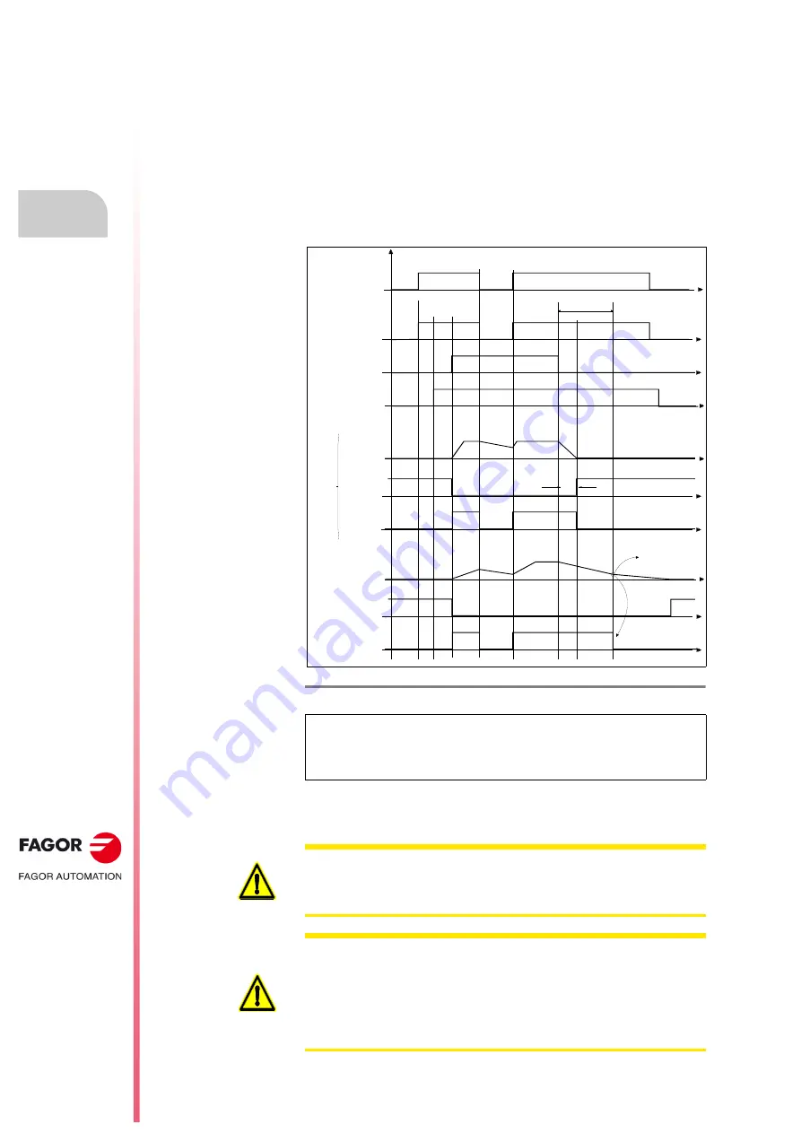
Deactivation of the Speed Enable input
When the Speed Enable input is set to 0 V DC, the internal velocity command
follows the stop ramp set by parameter and:
Situation 1
. The torque is kept active by braking the motor. When it stops,
variable SV5 (S00331) is activated. The motor has stopped in a time period
shorter than the one indicated by parameter GP3 (F00702). The torque
is canceled and the rotor is free.
Situation 2
. The torque is kept active by braking the motor. When it stops,
variable SV5 (S00331) is activated. The motor does not stop in a time
period set by parameter GP3 (F00702). The motor stops when its kinetic
energy runs out.
See also the internal parameter GP3 (F00702) and the internal variable
SV5 (S00331) in chapter 13 of the “man_dds_soft.pdf” manual that is
supplied with this one.
F. H3/60
Operating modes of functions Drive Enable and Speed Enable.
NOTE.
Also see in chapter 2 (
, pin 5 on PS power supplies),
, pin 5 on XPS power supplies) or (
, pin 5 on
RPS power supplies) corresponding to the System Speed Enable input
and its effect on the Speed Enable inputs of modular drives.
Dr
ive
Ena
ble
S
igna
l
S
pee
d E
nab
le
F
uncti
on
Ve
loc
ity
com
m
an
d
time
GP3
Trigger Error-4
Braking time < GP3
Proper braking < GP3
Braking time > GP3
SV
5:
nf
eedb
ac
k<
n
m
in
T
V
100:
Pa
rA
ct
iv
o
T
o
rq
ue
S
tat
e
C
ase
1: R
unn
in
g no
rm
al
ly
-F
ast mot
o
r
re
sp
onse
-
Re
al
S
pee
d
SV
5:
nfee
dba
ck
<nm
in
TV
10
0:
T
o
rq
ue
S
tat
us
C
a
se
2:
R
unni
ng
im
pr
oper
ly
-slo
w m
ot
o
r re
sp
o
n
se
-
Re
al
Spe
ed
With torq
ue
No torque
No torque
time
time
time
No torque
time
time
time
time
time
AS
1-
AS2
time
open contact
open contact
close contact
close contact
close contact
WARNING.
section) have the Drive Enable input as one channel of STO (
S
afe
T
orque
O
FF) safety function (PL d or SIL 2). Main contactor - KM1 may be used for
another channel. See chapter
in this manual.
WARNING.
In case of mains failure, the control circuit and its signals must
maintain their 24 V DC while the motors are braking.
On modular drives, the 24 V DC needed to activate the Drive Enable must
be obtained from a power supply that maintains its rated value during that
period of time. The PS-25B4 power supply, the APS-24 auxiliary power
supply and the regenerative XPS and RPS power supplies meet this
condition.
Содержание DDS APS-24
Страница 1: ...DRIVE DDS Hardware manual Ref 1912...
Страница 6: ...6 Ref 1912 DDS HARDWARE 6 I This page intentionally left blank...
Страница 9: ......
Страница 10: ......
Страница 11: ......
Страница 12: ......
Страница 16: ...Ref 1912 DDS HARDWARE 16...
Страница 20: ...Ref 1912 DDS HARDWARE 20...
Страница 179: ...3 Drives Ref 1912 179 DDS HARDWARE...
Страница 180: ...3 Drives Ref 1912 DDS HARDWARE 180...
Страница 200: ...4 AUXILIARY MODULES Auxiliary modules Ref 1912 DDS HARDWARE 200...
Страница 260: ...7 Cables Ref 1912 DDS HARDWARE 260...
Страница 397: ...Sales models 12 Ref 1912 397 DDS HARDWARE 12 9 Order example F H12 21 Order example...
Страница 404: ...13 Compatibility Ref 1912 DDS HARDWARE 404...
Страница 405: ......


