4.
Select the file name under which you want to save any changes to the file and click
OK
.
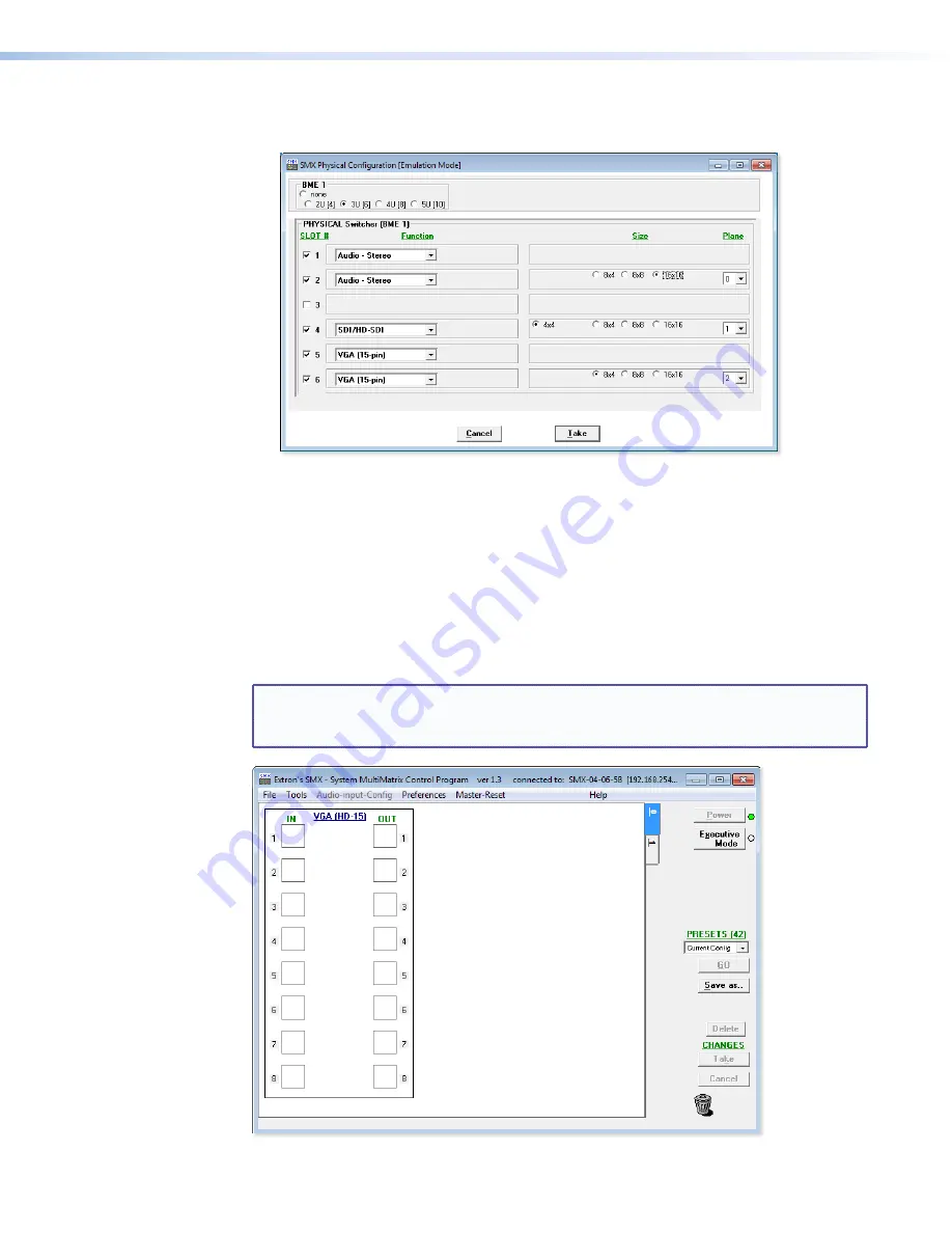
The SMX Physical Configuration [Emulation Mode] window appears.
5.
Select the signal type boards, board sizes, plane addresses, and matrix model for which
you are preparing a configuration and click
Take
.
6.
The SMX Control Program window opens (see
Using the Program
below).
Using the Program
At startup, the SMX Control Program window appears (see
figure 30
). The window displays
the current configuration of the SMX (the numbered boxes represent the video and audio
inputs and outputs and initially opens at the lowest plane). Each plane has a separate
numbered tab from 0-15, that are shown at the right side of the main window (in the
example below, only planes 0 and 1 are being used).
NOTE:
Each SMX system configuration varies per installation. The screens shown
throughout this section may look different from the ones displayed on your
computer.
Figure 30.
Video Inputs and Outputs on Plane 0 — No Ties
SMX System MultiMatrix Switcher • SMX Control Software
62


