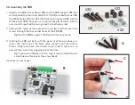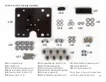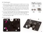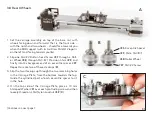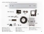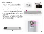
1. Identify parts
#33
, and
#34
, threaded hexagonal standoffs, each 12 mm long.
The straight hexagonal prisms are
#33
, the M4×8×12 Hex Standoffs. Parts
#34
are the “SemiHex” Standoffs, with a 10 mm hex section on the lower half only.
2. Also identify the eccentric spacers
#35
and the M4×10 Button-head Screws
#36
. The eccentric spacers have a hexagonal outline and an off-center hole.
The screws can be identified by their silver color, hex socket on the head, and
a length of approximately 10 mm below the head.
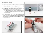
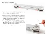
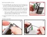
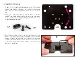
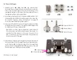
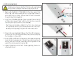
3. Turn the Carriage Plate upside down so that the bearings and Y Endstop are
facing down. Slip the M4×10 screws
into the two indicated holes (
A
), the
small-diameter holes that are not near the corners of the Carriage Plate.
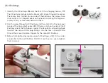
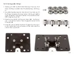
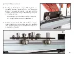
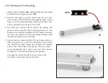
4. On the top side of the carriage, thread the two M4×8×12 hex standoffs
#33
onto the protruding screws (
B
).
3.5 Y Wheel Supports
(Continues on next page)
#33
#34
B
#35
#36
A
25
Содержание AxiDraw MiniKit 2
Страница 5: ...Part 1 Tools 5...
Страница 8: ...Part 2 The Base 8...
Страница 20: ...Part 3 The X Carriage 20...
Страница 35: ...Part 4 Y Belt and Z 35...
Страница 55: ...Part 5 Servo and wiring 55...
Страница 72: ...Part 6 Using AxiDraw MiniKit 72...

