background image

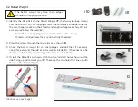
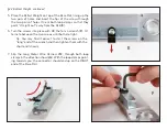
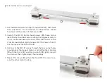
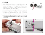
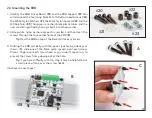
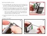
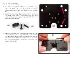
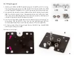
5.  Place the Ballast Weight on top of the Base Rail, lining up the 

two pairs of holes, and insert the tips of the screws through 

the two pairs of holes. Orient both loop clamps so that they 

point “straight out” away from the Rail (

E

). 

6.  Turn the screws into place with 

#2

, the Torx L-wrench (

F

).  Al-

ternate between the two screws until both are tight.

7.  Slip the Long Motor Wire Harness 

#12

, through both loop 

clamps in the direction shown (

G

). With the loop clamps point-

ing towards you, the connector should end up on the RIGHT 

end of the Base Rail.

F

E

Tip: You may find it easiest to start the screws on the 

“long” end of the wrench and then tighten them with the 

short end (shown).

G

§2.2 Ballast Weight, continued

11

Содержание AxiDraw MiniKit 2

Страница 1: ...Assembly Guide Model 2542 https emsl us 924 AxiDraw MiniKit 2 AxiDraw MiniKit 2 Assembly guide v 2 5 Last updated May 8 2021...

Страница 2: ...ge Assembly 21 3 2 Install the Y Endstop 22 3 3 Spacers shims and washers 23 3 4 X Carriage Idler Pulleys 24 3 5 Y Wheel Supports 25 3 6 Preset Y Eccentrics 28 3 7 Front X Wheels 29 3 8 Rear X Wheels...

Страница 3: ...e 62 5 7 Complete the wiring 64 5 8 Servo horn 68 5 9 Servo calibration 69 Part 6 Using AxiDraw MiniKit 72 6 1 Accessories 73 6 2 The AxiDraw User Guide 74 6 3 Special considerations for MiniKit 74 6...

Страница 4: ...ntact Whether you need help with an assembly step parts sup port assistance troubleshooting an issue or reassurance that you re building something correctly please feel wel come to drop us a line We a...

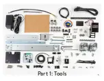
Страница 5: ...Part 1 Tools 5...

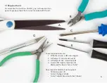
Страница 6: ...kit These required tools are 1 Either A scissors or B wire clippers 2 A Phillips 1 size screwdriver C 3 A Phillips 0 size screwdriver D 4 A small flat head screwdriver E Blade width about 2 mm or 5 64...

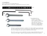
Страница 7: ...Wrench 6 8 mm Low profile Wrench 7 7 mm Low profile Wrench The three L wrenches are distinctive Only 2 is a Torx star shaped wrench And the only one with a ball end is the 2 mm L wrench 3 However the...

Страница 8: ...Part 2 The Base 8...

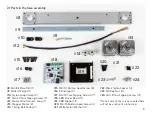
Страница 9: ...the base assembly 9 10 20 21 22 23 24 8 11 12 13 14 15 16 17 18 19 15 M3 14 Button head Screw 8 16 X Endstop 2 17 M4 12 Torx Tapping Screw 4 18 EBB Driver Board 1 19 EBB Support 1 20 M3 16 Button hea...

Страница 10: ...p edges and dull them if necessary using for example the side of a screwdriver blade C The ends may be sharp as well but they are mostly protected once installed 4 Orient the Base Rail as shown With t...

Страница 11: ...to place with 2 the Torx L wrench F Al ternate between the two screws until both are tight 7 Slip the Long Motor Wire Harness 12 through both loop clamps in the direction shown G With the loop clamps...

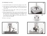
Страница 12: ...L wrench 3 3 Slide a pulley onto a motor shaft teeth up You may need to loosen the set screws to do so 4 Position the pulley with a set screw in front of the flat face and with its bottom 6 mm above...

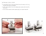
Страница 13: ...of the motor shaft using the short end of the hex wrench E 6 Tighten the second set screw on the pulley again using the short end of the hex wrench 7 Use the same method to add the second pulley to t...

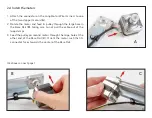
Страница 14: ...r and feed its pulley through the large hole in the Base Rail B taking care to not pull the cable out of the loop clamps 3 Feed the pulley on second motor through the large hole at the other end of th...

Страница 15: ...approximately 14 mm as measured below the head Note that there are also 4 similar looking but slightly longer M3 16 screws in the kit this step requires the 8 shorter ones 6 Slip four of the M3 14 sc...

Страница 16: ...head 2 Slip the screw through an X Endstop and then install it in the hole next to one of the timing belt pulleys B If there is a tab on the side of the X Endstop orient that tab down against the Base...

Страница 17: ...n washer over each screw A and then insert the screws through the four corner holes of the EBB B 3 Holding the EBB vertically with the power jack facing sideways as shown C slide one of the black nylo...

Страница 18: ...ch screw such that the teeth of the nut point in towards the EBB E Then tighten each screw with your 2 mm Ball end Hex L wrench 3 steadying the nut with a finger F 6 Check that the EBB and all four of...

Страница 19: ...ed below the head The screws go through the flange in the EBB support and into the two remain ing holes on the top of the Base Rail Use the Torx L wrench 2 to thread both screws into place and then ti...

Страница 20: ...Part 3 The X Carriage 20...

Страница 21: ...rriage Assembly 26 28 29 30 31 27 32 33 34 35 36 37 39 38 25 31 Stamped Washer M4 10 1 4 32 MF104 Ball Bearing 8 33 M4 8 12 Hex Standoff 2 34 M4 10 12 SemiHex Standoff 2 35 Eccentric Spacer 4 36 M4 10...

Страница 22: ...be identified by their black color wide head and length of approximately 12 mm as measured below the head 3 Align the two holes in the Y Endstop over the center two holes on the top of the Carriage P...

Страница 23: ...rance hole in the center Precision Shims 28 and 29 are both 8 mm in diameter They are precision machined washers distinguished by thickness 28 is 0 5 mm thick while 29 is 1 mm thick Side by side you s...

Страница 24: ...ther like tiny yet inedible metal sandwiches Slip one of the M4 12 Low Profile Screws 27 through each pair A 3 Place the four M4 8 0 5 Precision Shims 28 the thinnest ones over the four holes in the c...

Страница 25: ...line and an off center hole The screws can be identified by their silver color hex socket on the head and a length of approximately 10 mm below the head 3 Turn the Carriage Plate upside down so that t...

Страница 26: ...ith the Carriage Plate upside down again slip two Eccentric Spacers into the indicated holes E These are the two large di ameter holes opposite the hex standoffs The cylindrical part goes down into th...

Страница 27: ...e in each Eccentric Spacer F 9 Thread a SemiHex Standoff 34 onto each of the pro truding screws with the wide hexagonal surface down in contact with the Carriage Plate 10 Tighten both SemiHex Standoff...

Страница 28: ...been added thus far will be used to adjust the Y Carriage in a later step Rotate the two Eccentric Spacers using the 8 mm Low pro file Wrench 6 such that the screw heads are as far as possi ble from...

Страница 29: ...then through one of the thick 3 mm spacers 30 Repeat this to make two of these stackups A 4 Slip the two stackups up through the two corner holes at the front side of the Carriage Plate from the bott...

Страница 30: ...s should be secure in place but the outer clear plastic part of the wheel must be able to turn freely 3 7 Front X Wheels continued Tip In order to grip these nuts and tighten them you will need to kee...

Страница 31: ...wards you A 2 Slip one M4 22 Button head Screw 37 through a Roll er Wheel 38 through M4 8 1 Precision Shim 29 and finally into the hexagonal end of an eccentric spacer 37 Repeat to make two of these s...

Страница 32: ...lt the assembly forward while doing so D Final tightening will be in a subsequent step 6 Visual inspection Check that all four wheels are posi tioned in the channels on the sides of base rail and doub...

Страница 33: ...6 the 8 mm Low profile Wrench as in the previous case 3 6 on page 28 1 Check each rear wheel to make sure that it can be rotated If it cannot it is likely overly tight against the base rail Rotate the...

Страница 34: ...an be rotated with a little effort 5 Once Pair 1 is properly adjusted move on to Pair 2 Do not go back and forth between the two Again make small angle adjustments until there is no slack movement in...

Страница 35: ...Part 4 Y Belt and Z 35...

Страница 36: ...g 2 44 M4 8 8 Hex Standoff 2 4 1 Parts in the Y Belt and Z assemblies 40 41 44 46 45 42 43 47 51 48 49 50 52 45 M4 16 Button head Screw 2 46 Y EndCap 1 47 Timing Belt 1 48 Belt Spacer 1 49 Belt Retain...

Страница 37: ...nd of the Y Rail and lies over the two holes as shown C 4 Insert two M4 10 button socket cap screws 36 through the slot and into the square nuts Thread them into the nuts with the 2 5 mm Hex L wrench...

Страница 38: ...from each other once again like a tiny metal sandwich Then slip on the remaining 29 M4 8 1 Precision Shim A 3 Insert the remaining M4 Square Nut 41 into the channel on the opposite end of the Y rail B...

Страница 39: ...under the head 3 Slip these two screws through the two empty holes in the Y rail from the top empty side through to the bottom side which has the tensioning block and bearings A 4 On the bottom side t...

Страница 40: ...o M4 8 Torx Tapping Screws It may be easiest to hold the hold the Y Rail vertically while do ing so As you tighten it into place keep its edges lined up with the sides of the Y Rail A 4 Locate the two...

Страница 41: ...wo tall and straight M4 8 12 Hex Stand offs 33 on the left side of the X Carriage These are the fixed not adjustable wheels for the Y axis Use two of the M4 12 Low Profile Screws 27 and tighten them s...

Страница 42: ...ll as idler pulleys on the X and Y carriages The X carriage contains four idler pulleys arranged essentially in a square The Y carriage has one idler pulley at the front near the end effector pen hold...

Страница 43: ...belt pulleys and make sure that the teeth on the belt are point ing in so that they engage with the motors B 3 On the X Carriage set the belt as shown C looping around each of the four pulleys Refer...

Страница 44: ...t loop straight forward D 5 While holding the belt in tension make sure that it is flat and not twisted engaged in the teeth of both motors engaged between the flanges the four idler pulleys and not l...

Страница 45: ...2 Low Profile Screws 27 through a Roller Wheel 38 and set it on top of one of the SemiHex Standoffs 34 on the right side of the X Carriage 3 Hold the base of the SemiHex Standoff steady with the 10 mm...

Страница 46: ...pside down A 3 Identify the parts that we will use to anchor the belt in place The belt Spacer 48 the Belt Retaining Clip 49 and the M3 8 Button head Screw 50 The screw is distinguished by its 2 mm he...

Страница 47: ...each other 5 Holding the belt steady by the engaged teeth B pull the loose end to establish a little tension and en sure that the belt is still looped around the motors and pulleys As you do so check...

Страница 48: ...tly in place Keep it pushed forward so that it pinches the belt ends together in place 9 To fix the belt spacer in place use the Belt Retaining Clip 49 and the M3 8 Button head Screw 50 The retaining...

Страница 49: ...rly tensioned Note that from this point forward there will be extra fric tion when you move either carriage as it is moving the belt and thus the motors 11 Flip the machine back right side up and doub...

Страница 50: ...ose ends of the belt must not cross the red line shown here which is the inner face of the hex standoff by the tensioner on the bottom of the Y carriage If both loose ends are already behind this line...

Страница 51: ...e X Carriage on page 33 1 Position your hands as shown A with one hand on each side and fingers almost directly in line with either the two front side Y wheels or the two rear side Y wheels We will ca...

Страница 52: ...tated with a little effort 3 If the eccentric is difficult to turn you may need to slightly loosen the screw below it If it comes fully loose tighten it versus the SemiHex Standoff 4 Once Pair 1 is pr...

Страница 53: ...th two small holes and one large slot and a smaller rear mounting bracket with two smaller slots in it Check that the front face slides freely with respect to the mounting bracket 3 Put one of the M4...

Страница 54: ...and bring it to almost tight E 5 Align the Z slide mounting bracket and servo mount such that the path is clear for the second screw F 6 Add the second screw G Again ensure that the screw head engage...

Страница 55: ...Part 5 Servo and wiring 55...

Страница 56: ...Servo Motor 1 55 Servo Extension Cable 1 56 Spiral Wrap Tubing 1 57 Support Wire 1 5 1 Parts used in Servo and Wiring 53 54 55 56 57 58 59 60 61 58 Cable Ties 8 59 No 2 Tapping Screws 2 60 White Nylon...

Страница 57: ...o sition terminal block 2 One by one insert the four wire ends into the terminal block and tighten them firmly with your small flat head screwdriver The wires go into the lowest four positions motor 1...

Страница 58: ...ar ness A 2 Guide the wires over through the vertical slot above the other Wire Harness B 3 Connect the four wire ends to the upper four positions of the EBB terminal block C and tighten each well The...

Страница 59: ...e servo motor A 3 Starting from the body of the Servo Motor wrap the Spiral Wrap Tubing 56 around the servo cable and support wire As you do so keep the cable and wire together and keep the loop end n...

Страница 60: ...st wire on the servo cable connects to the black wire on the extension cable 5 Continue wrapping the spiral wrap including coarsely over the connection between the two cables G H 6 When you reach the...

Страница 61: ...hese screws are small and black with a Phillips head and a length of about 6 mm under the head 3 Put one of the screws on the tip of your 0 Phillips screw driver B and steady it with a finger for inse...

Страница 62: ...hole in the servo mount A Then loop the narrow end through its square locking piece to close it B 2 Pull the loose end of the cable tie to take out the slack As you do so guide the support wire loop...

Страница 63: ...e excess length of the cable tie with scissors or wire clippers D 4 Add a second cable tie looping around the wrapped ca ble forward through the uppermost rectangular hole in the servo Mount E Cinch i...

Страница 64: ...e horizontal beam of the EBB support A 2 Cinch the cable tie tight and cut off the excess length B 3 Pull the free end of the servo extension cable in through the vertical slot of the EBB support belo...

Страница 65: ...vertical slot in the EBB support and out of the lowest horizontal slot D 5 Slip the end of that cable tie through the loop at the end of the support wire E 6 Close and cinch the cable tie F pull it t...

Страница 66: ...bottom three horizontal pins below the terminal block on the EBB driver board The white wire goes forward and the black wire back towards the edge of the board H 9 Loop a cable tie around the horizon...

Страница 67: ...e tie into the top of vertical slot in the EBB Support out of the highest horizontal slot and around the wrapped cable and support J 11 Cinch that cable tie very tight to support the cable guide verti...

Страница 68: ...ead screw 61 The nylon spacer is a short white plastic tube and the screw can be identified by its wide head silver color and length of about 6 mm under the head 3 Prop up the flat part of the servo h...

Страница 69: ...xiDraw Control select the Setup tab There B select the following settings 4 Click the Apply button several times to toggle the pen po sition between the pen up and pen down positions If all is working...

Страница 70: ...e more times so that you can feel it move between the two positions 7 Stop toggling when you are certain that the servo is in the pen down position 8 Pull the Z Slide up slightly and press the servo h...

Страница 71: ...th AxiDraw Control F If things are set up properly it will move between two vertical positions between the maximum pen up and maximum pen down positions described previously C It may not and does not...

Страница 72: ...Part 6 Using AxiDraw MiniKit 72...

Страница 73: ...clip can be found in the main AxiDraw User Guide available at https axidraw com guide The easel comes as a bare piece of hardboard plus a packet of rubber feet Six rubber feet are included Press four...

Страница 74: ...User Guide is applicable to the MiniKit there are several key differences that you should be aware of 6 3 1 Pause button The pause button on AxiDraw MiniKit is located directly on the EBB driver board...

Страница 75: ...o be operated at relatively low speeds compared to larger models that have a wider stance and much higher mass For best performance speeds below 50 maximum are recommended for both pen down and pen up...

Отзывы:

Похожие инструкции для AxiDraw MiniKit 2