ESAB ET 220i AC/DC Скачать руководство пользователя страница 69

ET 201I AC/DC

0-5346 

KEY SPARE PARTS 

6-3

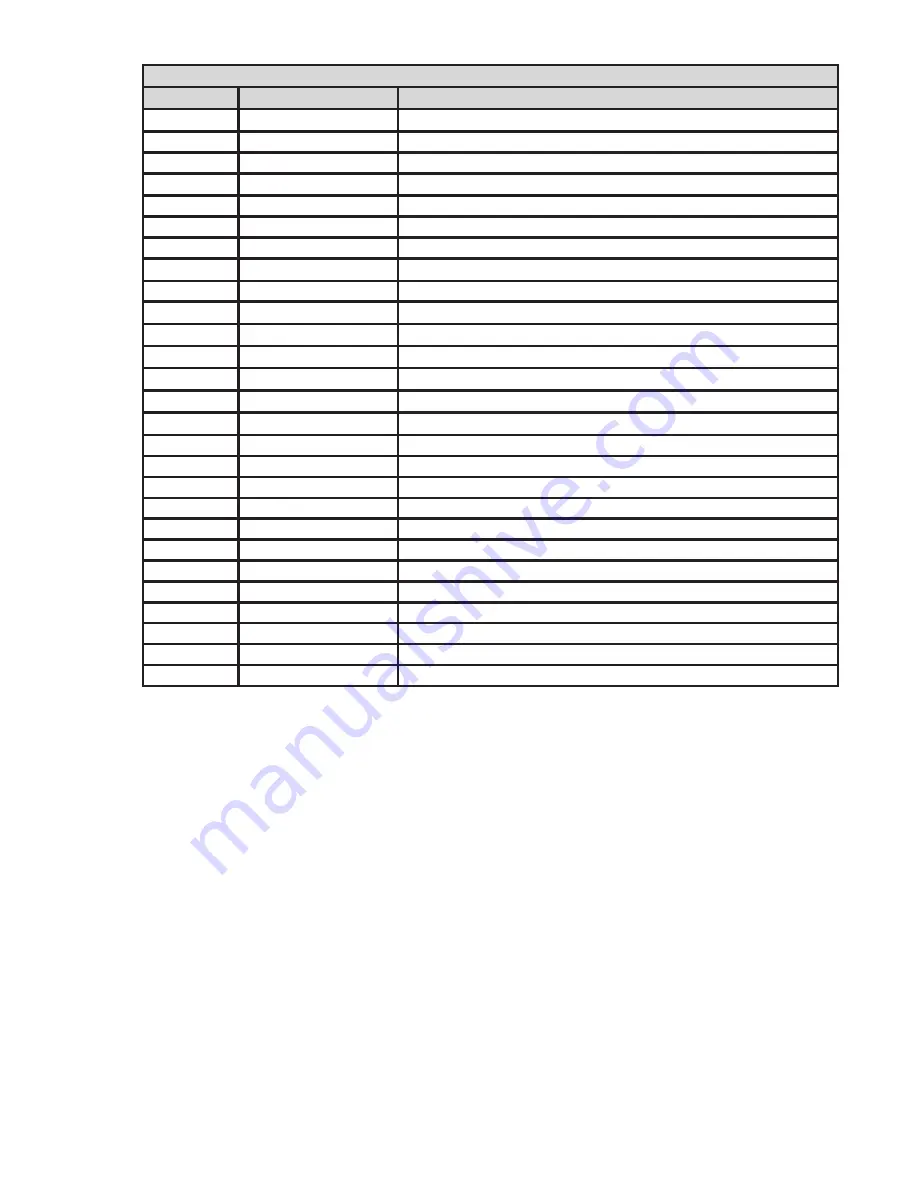
ET 220i AC/DC Spare Parts

Item

Part Number

Description

1

W7006300

Clear Control Panel Cover

2

W7006301

Gas Outlet, Front Panel

2

W7006301

Gas Inlet, Rear Panel

4

W7006500

Knob, Control

5

W7006323

PCB Secondary Rectifier

6

W7006433

PCB Control

7

W7006434

PCB Primary Inverter

8

W7006307

PCB, Display

9

W7006427

REL02

10

W7006326

Transformer, Inverter

11

W7006439

Switch, On/Off

12

W7006426

Rectifier, Bridge, Mains Supply

13

W7006314

Cable Assy, 8 Pin Remote

14

W7006431

Cable Assy, 4 Pin CAN

13

667.8377.0

Cable Assy, 14 Pin Remote

16

W7006315

Solenoid 24VDC

17

W7006316

Fan 12VDC

18

W7006317

Inductor HF

20

W7006319

IGBT

21

W7006740

Diode, Output

22

W7006425

HF Filter

23

W7006430

Panel Mount Dinse Socket 50mm

2

24

W6000000

Thermal Sensor

25

W7006441

Panel, Control (User Interface)

26

W7006429.

Panel, Front

27

W7006440

Panel, Rear

28

W7006428

Transformer, Control

Table 6-1: Spare Parts

Содержание ET 220i AC/DC

Страница 1: ...ESAB ET 220i AC DC Art A 12839_AB Operating Manual 4010062 R vision AD Issue Date October 26 2016 Manual No 0 5346 esab com HF START HF PULSE CURRENT AC DC...

Страница 2: ...refore please take the time to read the entire manual especially the Safety Precautions They will help you to avoid potential hazards that may exist when working with this product YOU ARE IN GOOD COMP...

Страница 3: ...esab com Copyright 2015 by ESAB All rights reserved Reproduction of this work in whole or in part without written permission of the publisher is prohibited The publisher does not assume and hereby di...

Страница 4: ...ereof contained in this manual and accompany ing labels and or inserts when installed operated maintained and repaired in accordance with the instructions provided This equipment must be checked perio...

Страница 5: ...ference 3 2 3 07 Electromagnetic Compatibility 3 3 3 08 Power Source Controls Indicators and Features 3 4 3 09 Setup for TIG GTAW Welding 3 10 3 10 TIG GTAW Programming Mode 3 13 3 11 TIG GTAW Welding...

Страница 6: ...1 5 01 Basic Troubleshooting 5 1 5 02 Power Source Problems 5 3 5 03 Routine Service and Calibration Requirements 5 4 5 04 Cleaning the Welding Power Source 5 5 SECTION 6 KEY SPARE PARTS 6 1 6 01 Key...

Страница 7: ...is unprotected when the arc is struck 3 The workplace must be suitable for the purpose be free from drafts 4 Personal safety equipment Always wear recommended personal safety equipment such as safety...

Страница 8: ...tective clothing Protect bystanders with suitable screens or curtains FIRE HAZARD Sparks spatter can cause fire Make sure therefore that there are no inflammable materials nearby NOISE Excessive noise...

Страница 9: ...mblies is identified only by the specification or part number printed on the shipping container Record these numbers on the bottom of page ii for future reference 2 04 Description The ET 220i AC DC is...

Страница 10: ...statement of the time it may be operated at its rated welding current output with out exceeding the temperature limits of the insulation of the component parts To explain the 10 minute duty cycle peri...

Страница 11: ...20A 3 phase Effective Input Current I1eff note2 27 6A 208V 1 phase 25 0A 230V 1 phase 15 2A 460V 1 phase 16 8A 208V 3 phase 15 2A 230V 3 phase 8 2A 460V 3 phase Maximum Input Current I1max 37 3A 208V...

Страница 12: ...ESAB cannot guarantee full welding output power or duty cycle on every brand or type of generator ESAB recommends that when selecting a generator that the particular power source generator combina ti...

Страница 13: ...nit 3 01 Environment These units are designed for use in environments with increased hazard of electric shock as outlined in IEC 60974 1 A Examples of environments with increased hazard of electric sh...

Страница 14: ...y Introduction The importance of correct installation of high frequency welding equipment cannot be overemphasized Interference due to high frequency initiated or stabilized arc is almost invariably t...

Страница 15: ...ing Electromagnetic Emissions 1 Mains Supply Welding equipment should be connected to the mains supply according to the manufacturer s recommenda tions If interference occurs it may be necessary to ta...

Страница 16: ...way insert plug and rotate threaded collar fully clockwise The socket information is included in the event the supplied cable is not suitable and it is necessary to wire a plug or cable to interface w...

Страница 17: ...e at Mains voltage potential 6 Mains Supply Lead The ET 220i AC DC is fitted with a heavy duty mains supply lead 10ft long cable no plug 7 Gas Inlet The Shielding Gas Inlet connection is used to suppl...

Страница 18: ...olt free relay contact Weld Amps 0A 10 Volt free relay contact Weld Amps 0A 11 Not used 12 Not used 13 Not used 14 Not used Table 3 2 14 Pin Interconnection Control Plug Configuration T 4T 2T Art A 12...

Страница 19: ...e modes are Electrode DC HF Electrode DC AC and HF AC 18 HF high frequency indicator light This light will illuminate when the power source is in GTAW 2T or 4T HF welding mode 19 Electrode Negative in...

Страница 20: ...r selected the status indictor adjacent to the volt meter will illuminate to show the units of the welding parameter When welding the volt meter will display actual welding voltage At the completion o...

Страница 21: ...art Amps Welding Parameter is selected in SMAW mode 41 Electrode Diameter indicator light This light will illuminate when the Electrode Diameter Welding Parameter is selected 42 Up Slope indicator lig...

Страница 22: ...rminals It is essential however that the male plug is inserted and turned securely to achieve a sound electrical connection C Connect the work lead to the Worklead welding terminal bottom Welding curr...

Страница 23: ...ET 220I AC DC Manual 0 5346 INSTALLATION OPERATION AND SETUP 3 11 T 4T 2T 10 17 Art A 12844 Figure 3 7 Setup for TIG Welding...

Страница 24: ...g Type Selection DC HF TIG AC Liftarc TIG DC Liftarc TIG AC HF TIG Then select a Welding Mode by pressing the WELDING MODE 10 button Welding Mode Welding Mode Selection 2T Normal Mode T 4T 2T 4T Latch...

Страница 25: ...F DC Negative welding output mode The HF LED 18 and the DC Negative LED 19 will illuminate WARNING In HF operating mode high voltage pulses are generated within the power source to provide contactless...

Страница 26: ...once the torch trigger switch has been pressed This control is used to dramatically reduce weld porosity at the start of a weld 0 1 10 0 seconds 0 1 Start Current AS This parameter operates in GTAW m...

Страница 27: ...is the current at the end of the down slope current ramp The welding current will remain at the Crater Current value until the Crater Current Time has elapsed at which time the welding current will ce...

Страница 28: ...5 10 90 positive welding current 35 Electrode Diameter ET 220i AC DC Set this parameter to the tungsten electrode size being used 040 1 8 Inch 3 32 AC frequency This parameter operates in AC mode only...

Страница 29: ...GTAW welding arc Maximum weld penetration is achieved when the AC BALANCE is set to 10 Maximum cleaning of heavily oxidized aluminium or magnesium alloys is achieved when the WAVE BALANCE is set to 90...

Страница 30: ...Left Display Parameter Value Right Display Factory Setting Ignition Peak Correction The ignition peak current is set after ignition to provide stabilisation of the arc A different peak current is save...

Страница 31: ...Diameter LED 41 and inch LED 29 are illuminated Use the Multi Function Control 24 to adjust the Electrode size being used Press and hold the WELDING MODE 10 button then press the SAVE 53 button Press...

Страница 32: ...ssible to select any TipTronic jobs Use the BACK button 22 or FORWARD button 22 to switch between TipTronic jobs and all main parameters T 4T 2T Art A 12847 Figure 3 10 Tip Tronic Operation Save a Tip...

Страница 33: ...e SAVE button 53 Set a TipTronic Job as Active Press the SAVE button 53 The display will show the Job Number identification the job set and job number Use the Multi Function Control 24 to select the j...

Страница 34: ...ce via 50mm Dinse type terminals It is essential however that the male plug is inserted and turned securely to achieve a sound electrical connection C Select Stick and electrode positive mode with the...

Страница 35: ...A 12849 Figure 3 12 Stick Programming Mode Press the WELDING MODE 10 button to select SMAW mode The SMAW LED 11 will illuminate Following SMAW operating modes are available DC Negative mode DC Negativ...

Страница 36: ...6 1 5mm 20 40 Amps 3 32 2 5mm 45 100 Amps 1 8 3 2mm 75 140 Amps 5 32 4 0mm 130 190 Amps Table 3 7 Normal Welding Current for SMAW Electrode sizes Parameter Range LED Code Left Display Parameter Value...

Страница 37: ...played Note that even during welding these settings can be adjusted and changed Parameter Range LED Code Left Display Parameter Value Right Display Factory Setting Arc Dynamic Arc Force Arc Force is e...

Страница 38: ...it to save the settings Menu item Range LED Code Left Display Parameter Value Right Display Factory Setting C02 Water Pump Error Message Display Set this to ON if a water cooler without a suitable int...

Страница 39: ...l Minimum current is enabled The minimum currents are electrode 0 040 0 080 10A electrode 3 32 15A electrode 1 8 20A ON OFF OFF C09 SMAW mode only Set to OFF OFF OFF Table 3 10 User Specific Menus 3 1...

Страница 40: ...3 All control panel LED s will light up briefly to confirm the Soft Reset has been completed After 5 seconds all the control panel LED s will light again briefly to confirm the Master Reset has been c...

Страница 41: ...ile the fan is running the fan test is halted Art A 12855 T 4T 2T Figure 3 18 Fan Test Water Pump Test Only for water pump with Net Connection interface Press and hold the FORWARD button 22 Press the...

Страница 42: ...ow pressure chambers 4 DO NOT use the regulator flowmeter as a control valve When downstream equipment is not in use for extended periods of time shut off the gas at the cylinder valve and release the...

Страница 43: ...nd the adjustment screw knob fully disengaged pressurize as follows 1 Stand to one side of regulator flowmeter and slowly open the cylinder valve If opened quickly a sudden pressure surge may damage i...

Страница 44: ...ource 3 After gas is drained completely disengage adjusting screw and close downstream equipment valves 4 Before transporting cylinders that are not secured on a cart designed for such purposes remove...

Страница 45: ...ing connected With the foot control connected the power source will only display minimum preview Amps until the foot con trol is depressed then it displays actual welding current when welding Pressing...

Страница 46: ...ET 220I AC DC INSTALLATION OPERATION AND SETUP Manual 0 5346 3 34 This Page Intentionally Blank...

Страница 47: ...igher current settings using larger electrodes sizes short runs for larger electrode deposits or tempering in a furnace Hydrogen controlled Electrodes must be used for this application B Austenitic ma...

Страница 48: ...on Gravity Fillet Weld Art A 07689 Figure 4 3 Horizontal Position Butt Weld Art A 07690 Figure 4 4 Horizontal Vertical HV Position Art A 07691 Figure 4 5 Vertical Position Butt Weld Art A 07692 Figure...

Страница 49: ...ints In general surfaces being welded should be clean and free of rust scale dirt grease etc Slag should be removed from oxy cut sur faces Typical joint designs are shown in Figure 4 9 Gap varies from...

Страница 50: ...roken again A little practice will soon remedy both of these faults Art A 07696_AB 20 1 6 mm 1 16 Figure 4 10 Striking an Arc Arc Length The securing of an arc length necessary to produce a neat weld...

Страница 51: ...line of the fillet and about 45 from the vertical Some electrodes require to be sloped about 20 away from the perpendicular position to prevent slag from running ahead of the weld Refer to Figure 4 13...

Страница 52: ...eld Metal Molten steel shrinks approximately 11 per cent in volume on cooling to room temperature This means that a cube of molten metal would contract approximately 2 2 per cent in each of its three...

Страница 53: ...es of a joint by two welders is often successful in eliminating distortion C Restraint of Parts Forcible restraint of the components being welded is often used to prevent distortion Jigs positions and...

Страница 54: ...smaller diameter electrode C Insufficient gap C Allow wider gap 3 Non metallic particles are trapped in the weld metal A Non metallic particles may be trapped in undercut from previous run A If a bad...

Страница 55: ...more room in joint for manipulation of the electrode E Electrode too large for joint E Use smaller gauge electrode F Insufficient deposit time at edge of weave F Pause for a moment at edge of weave t...

Страница 56: ...windy environment E Shield the weld area from the wind F Electrode damaged ie flux coating incomplete F Discard damaged electrodes and only use electrodes with a complete flux coating 7 Crack occurri...

Страница 57: ...he welding application Welds Made With or Without Addition of Filler Metal Work Piece Can Be Any Commercial Metal Gas Cup Either Ceramic High lmpact or Water Cooled Metal Inert Gas Shields Electrode a...

Страница 58: ...welding of high strength Cr Mo steels used at elevated temperatures ER308L ER309L ER316L For stainless steels Stainless pipes tubing architectural uses etc R4043 For stainless steels Stainless pipes...

Страница 59: ...in bead are widely spaced apart Travel speed too fast Reduce travel speed 4 Weld bead too wide or excessive bead build up or excessive penetration in butt joint Travel speed too slow Increase travel s...

Страница 60: ...o large for the welding current A Select the right size tungsten electrode Refer to Table 4 3 ESAB Tungsten Electrode Selection Chart B The wrong electrode is being used for the welding job B Select t...

Страница 61: ...ave an Accredited ESAB Service Provider check the power source EEProm checksum error Communication with EEProm is faulty Switch machine off then back on Perform a master reset If the problem continues...

Страница 62: ...SAB Service Provider check the power source Voltage Detection plug socket Voltage Detection Error in module 2 Have an Accredited ESAB Service Provider check the power source Torch Remote Control Remot...

Страница 63: ...t A B Replace primary control fuse Have an Accredited ESAB Service Provider check primary circuit 3 Error Code E01 is displayed and unit will not commence welding when the torch trigger switch is depr...

Страница 64: ...Tested Minimum Insulation Resistance M Input circuit including any connected control circuits to welding circuit including any connected control circuits 5 All circuits to exposed conductive parts 2 5...

Страница 65: ...by an accredited ESAB service provider Testing Requirements Output current A to be checked to ensure it falls within applicable ESAB power source specifications Output Voltage V to be checked to ensur...

Страница 66: ...ET 220I AC DC POWER SOURCE PROBLEMS AND ROUTINE SERVICE REQUIREMENTS Manual 0 5346 5 6 This Page Intentionally Blank...

Страница 67: ...ET 201I AC DC 0 5346 KEY SPARE PARTS 6 1 SECTION 6 KEY SPARE PARTS This Page Intentionally Blank See next two pages...

Страница 68: ...ET 201I AC DC KEY SPARE PARTS 0 5346 6 2 6 01 Key Spare Parts A 12885_AB Figure 6 1 Spare Parts...

Страница 69: ...W7006326 Transformer Inverter 11 W7006439 Switch On Off 12 W7006426 Rectifier Bridge Mains Supply 13 W7006314 Cable Assy 8 Pin Remote 14 W7006431 Cable Assy 4 Pin CAN 13 667 8377 0 Cable Assy 14 Pin...

Страница 70: ...ET 201I AC DC KEY SPARE PARTS 0 5346 6 4 This Page Intentionally Blank...

Страница 71: ...extern Y1 X12 2 X12 1 L1 2 1 X4 X1 L1 T1 L2 T2 L3 T3 Q1 L2 L3 LP2 LP3 A4 AC AC AC 3 LP5 LP6 A1 REL02 X1 A5 Mapro X1 7 X1 8 X12 5 A2 DRV06 LP6 LP7 LP8 X3 2 X3 3 X3 4 braun brown wei white schwarz black...

Страница 72: ...ET 220I AC DC APPENDIX Manual 0 5346 A 2 REVISION HISTORY Cover Date Rev Change s 05 07 15 AA Manual release 01 15 16 AB Updated Liftarc TIG wording Section 6 art spart parts list and Appendix art...

Страница 73: ......

Страница 74: ...x 46 31 50 92 22 ESAB international AB Gothenburg Tel 46 31 50 90 00 Fax 46 31 50 93 60 SWITZERLAND ESAB AG Dietikon Tel 41 1 741 25 25 Fax 41 1 740 30 55 UKRAINE ESAB Ukraine LLC Kiev Tel 38 044 501...

Отзывы: