


ESAB ET 186i AC/DC
INSTALLATION, OPERATION AND SETUP 3-20 Manual 0-5425
c) Place the TIG torch gas hose to the gas outlet and tighten with a wrench. Caution: DO NOT over tighten.
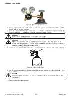
4. Using a secured Argon cylinder, slowly crack open then close the cylinder valve while standing off to the side of the valve. This
will remove any debris that may be around the valve & regulator seat area.
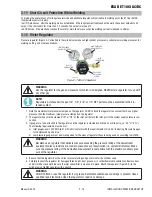
5. Install the regulator (for details of VICTOR regulator, please refer to 3.18) and tighten with a wrench.
6. Connect one end of the supplied gas hose to the outlet of the Argon regulator and tighten with a wrench. Caution: DO NOT over
tighten.
7. Connect the other end of the supplied gas hose to the gas inlet fitting on the rear panel of the welder and tighten with a wrench.
Caution: DO NOT over tighten.
8. Open the Argon Cylinder Valve to the fully open position.
9. Connect the ground (work) clamp to your work piece.
10. Set the DOWN SLOPE control knob to the desire weld current ramp down time.
11. Set the weld current control knob to the desired amperage.
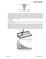
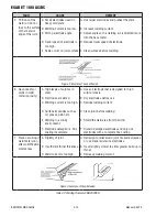
12. The tungsten must be ground to a blunt point in order to achieve optimum welding results. It is critical to grind the tungsten
electrode in the direction the grinding wheel is turning.
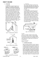
13. Install the tungsten with approximately 1/8" (3.2mm) to ¼" (6.0mm) sticking out from the gas cup, ensuring you have correct
sized collet.
14. Tighten the back cap then open the valve on the torch.
15. Plug the power cable into the appropriate outlet, and turn the switch to the “ON" position. The power L.E.D. light should illuminate.
Set the “Process Selection Switch" to LIFT TIG.
16. You are now ready to begin TIG Welding.
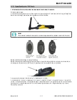
NOTE!
When the ET 186i AC/DC is used with a Remote Foot Control in, depress foot control to maximum to al-
low max current to be previewed/adjusted on the front panel. To avoid premature arcing, please ensure
the TIG Torch is located away from your work piece.
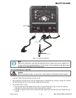
3.15 Setup for STICK (SMAW) Welding
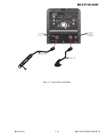
A. Connect the Electrode Holder lead to the positive welding terminal (+). If in doubt, consult the electrode manufacturer. Welding
current flows from the Power Source via heavy duty bayonet type terminals. It is essential, however, that the male plug is inserted
and turned securely to achieve a sound electrical connection.
B. Connect the work lead to the negative welding terminal (-). If in doubt, consult the electrode manufacturer. Welding current flows
from the power source via heavy duty bayonet type terminals. It is essential, however, that the male plug is inserted and turned
securely to achieve a sound electrical connection.
C. Select STICK mode with the process selection control (refer to Section 3.08.7 for further information)
!
WARNING
Before connecting the work clamp to the work and inserting the electrode in the electrode holder make
sure the mains power supply is switched off.
!
CAUTION
Remove any packaging material prior to use. Do not block the air vents at the front or rear of the
Welding Power Source.
!
CAUTION
Loose welding terminal connections can cause overheating and result in the male plug being fused in
the bayonet terminal.


