ESAB ET 186i AC/DC Скачать руководство пользователя страница 10

ESAB ET 186i AC/DC

INTRODUCTION                                                                             2-2                                                                        Manual 0-5425

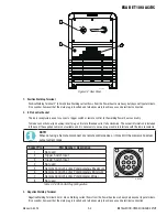
2.05  User Responsibility

This equipment will perform as per the information contained 
herein when installed, operated, maintained and repaired in 
accordance with the instructions provided. This equipment 
must be checked periodically. Defective equipment (includ-
ing welding leads) should not be used. Parts that are broken, 
missing, plainly worn, distorted or contaminated, should be 
replaced immediately. Should such repairs or replacements 
become necessary, it is recommended that such repairs be 
carried out by appropriately qualified persons approved by 
ESAB. Advice in this regard can be obtained by contacting an 
Accredited ESAB Distributor.
This equipment or any of its parts should not be altered from 
standard specification without prior written approval of ESAB. 
The user of this equipment shall have the sole responsibil-
ity for any malfunction which results from improper use or 
unauthorized modification from standard specification, faulty 
maintenance, damage or improper repair by anyone other than 
appropriately qualified persons approved by ESAB.

2.06  Transporting Methods

This unit is equipped with a handle for carrying purposes.

!


WARNING

ELECTRIC SHOCK can kill. DO NOT TOUCH 
live electrical parts. Disconnect input 
power conductors from de-energized sup-
ply line before moving the welding power 
source.

!


WARNING

FALLING EQUIPMENT can cause serious 
personal injury and equipment damage.

Lift unit with handle on top of case.
Use handcart or similar device of adequate capacity.
If using a fork lift vehicle, place and secure unit on a proper 
skid before transporting.
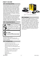
2.07  Packaged Items

•  ET 186i AC/DC Inverter Power Source
•   ESAB 200 Amp Electrode Holder with 13ft (4m) Lead
•  ESAB 200 Amp Work Clamp with 10ft (3m) Lead
•  26 TIG Torch 13ft (4m) Lead with Integrated Controls & 

Accessory

•  9ft (2.75m) Power Cord and NEMA6-50P 230V AC Plug
•  Victor Argon Flow Gauge & 12.5 ft (3.8m) Hose
•  4 General Purpose Stick Electrodes (E6013)
•  Shoulder Strap
•  Operating Manual & CD
•  ESAB Cap

Art# A-13114

Figure 2-1: ET 186i AC/DC Packaged System
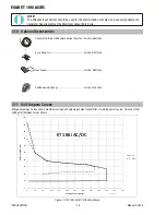
2.08  Duty Cycle

The rated duty cycle of a Welding Power Source, is a statement 
of the time it may be operated at its rated welding current 
output without exceeding the temperature limits of the insula-
tion of the component parts.  To explain the 10 minute duty 
cycle period the following example is used.  Suppose a Welding 
Power Source is designed to operate at a 20% duty cycle, 200 
amperes at 18.0 volts.  This means that it has been designed 
and built to provide the rated amperage (200A) for 2 minutes, 
i.e. arc welding time,  out of every 10 minute period (20% of 
10 minutes is 2 minutes).  During the other 8 minutes of the 
10 minute period the Welding Power Source must idle and be 
allowed to cool. The thermal cut out will operate if the duty 
cycle is exceeded. 

Содержание ET 186i AC/DC

Страница 1: ...3163339 R vision AA Issue Date June 1 2016 Manual No 0 5425 Operating Manual ESAB ET 186i AC DC Inverter Arc Welder esab com Art A 13113...

Страница 2: ...take the time to read the entire manual especially the Safety Precautions They will help you to avoid potential hazards that may exist when working with this product YOU ARE IN GOOD COMPANY The Brand...

Страница 3: ...served Reproduction of this work in whole or in part without written permission of the publisher is prohibited The publisher does not assume and hereby disclaims any liability to any party for any los...

Страница 4: ...reof contained in this manual and accom panying labels and or inserts when installed operated maintained and repaired in accordance with the instructions provided This equipment must be checked period...

Страница 5: ...ns Supply Voltage Requirements 3 1 3 05 High Frequency Introduction 3 2 3 06 High Frequency Interference 3 2 3 07 Electromagnetic Compatibility 3 3 3 08 ET 186i AC DC Power Source Controls Indicators...

Страница 6: ...1 5 01 Basic Troubleshooting 5 1 5 02 Power Source Problems 5 1 5 03 Routine Service and Calibration Requirements 5 2 5 04 Cleaning the Welding Power Source 5 4 SECTION 6 KEY SPARE PARTS 6 1 6 01 Powe...

Страница 7: ...rted up no one is unprotected when the arc is struck 3 The workplace must be suitable for the purpose be free from drafts 4 Personal safety equipment Always wear recommended personal safety equipment...

Страница 8: ...ter lens and wear protective clothing Protect bystanders with suitable screens or curtains FIRE HAZARD Sparks spatter can cause fire Make sure therefore that there are no inflammable materials nearby...

Страница 9: ...DC provides excellent welding performance across a broad range of applications when used with the correct welding consumables and procedures The follow ing instructions detail how to correctly and saf...

Страница 10: ...d sup ply line before moving the welding power source WARNING FALLING EQUIPMENT can cause serious personal injury and equipment damage Lift unit with handle on top of case Use handcart or similar devi...

Страница 11: ...wer Source Applicable Standards Approvals CSA E60974 1 00 UL60974 1 IEC 60974 1 Number of Phases 1 Nominal Supply Frequency 50 60Hz Welding Current Range STICK Mode 5 170A DC Stick 10 170A AC Stick We...

Страница 12: ...maximum voltage and amperage output capabilities of welding power source Curves of other settings fall between curves shown 60 70 80 90 100 e volts ET 186i AC DC 0 10 20 30 40 50 0 20 40 60 80 100 12...

Страница 13: ...using in such areas A Examples of environments with increased hazard of electric shock are 1 In locations in which freedom of movement is re stricted so that the operator is forced to perform the work...

Страница 14: ...lar to a radio transmitter The machine should NOT be used in the vicinity of blasting operations due to the danger of premature firing WARNING It is also possible that operation close to computer inst...

Страница 15: ...d television transmitters and receivers 3 Computer and other control equipment 4 Safety critical equipment e g guarding of industrial equipment 5 The health of people around e g the use of pace makers...

Страница 16: ...and position e g ship s hull or building steelwork a connection bonding the work piece to earth may reduce emissions in some but not all instances Care should be taken to prevent the earthing of the...

Страница 17: ...in the event the supplied cable is not suitable and it is necessary to wire a plug or cable to interface with the 8 pin receptacle NOTE When not using a Remote disconnect any remote control device or...

Страница 18: ...r check the power source b Primary Circuit Overcurrent This is due to primary circuit component s malfunctioning which results in excessive primary circuit current Switch OFF the power source immediat...

Страница 19: ...n 4T TIG modes only and is used to set the time for the weld current to ramp up after the torch trigger switch has been pressed then released from Initial Current to High or Weld Current Press hold Tr...

Страница 20: ...ameters that are applicable to a specific PROCESS MODE or TRIGGER SELECTION will light when using the FORWARD or BACK programming switches Secondly during the welding process the fol lowing sequence i...

Страница 21: ...mponents are at Mains voltage potential 21 Shielding Gas Inlet Unit has a 5 8 Inert gas fitting suitable for connection of a gas hose to a regulated Shielding Gas Supply The Shielding Gas inlet is loc...

Страница 22: ...ld Current This parameter sets the TIG WELD current when PULSE is OFF This parameter also sets the STICK weld current Amps 5 to 170A DC STICK mode 10 to 170A AC STICK mode Arc Force STICK Mode only Ar...

Страница 23: ...LIFT TIG or HF TIG mode Press the MODE switch to toggle between AC and DC welding output Press FORWARD or BACK to cycle through available programming functions Use the Multi Function Control to adjus...

Страница 24: ...has been depressed Note The maximum initial current available will be limited to the set value of the weld current Amps 5 to 200 Amps DC TIG mode 30 to 200 Amps AC LIFT TIG mode 10 to 200A AC HF TIG...

Страница 25: ...t to ramp down after the torch trigger switch has been pressed to crater current This control is used to eliminate the crater that can form at the completion of a weld V SEC Hz Volts 0 0 to 25 0 secon...

Страница 26: ...is achieved when the WAVE BALANCE control is set to 10 Maximum cleaning of heavily oxidized aluminium or magnesium alloys is achieved when the WAVE BALANCE control is set to 65 V SEC Hz Volts 10 to 6...

Страница 27: ...her pressure than the maximum rated pressure stamped on the regulator 2 The regulator body will be stamped IN or HP at the inlet port Attach the inlet port to the system supply pressure con nection 3...

Страница 28: ...remove it from the regulator WARNING Stand to the side of the cylinder opposite the regulator when opening the cylinder valve Keep the cylinder valve between you and the regulator For your safety NEV...

Страница 29: ...ith roller potentiometer Control module with roller potentiometer and integrated on off switch Additional On Off Switch Cartridge in a Sealed Plastic Bag Additional On Off Switch Remote Amperage Contr...

Страница 30: ...nnect the TIG torch trigger switch via the 8 pin socket located on the front of the power source as shown below The TIG torch will require a trigger switch to operate in Lift TIG or HF TIG Mode NOTE S...

Страница 31: ...sure to wear all appropriate and recommended safety equipment 1 Switch the ON OFF Switch located on the rear panel to OFF 2 Connect the ground work clamp cable to positive output terminal It is essent...

Страница 32: ...ble into the appropriate outlet and turn the switch to the ON position The power L E D light should illuminate Set the Process Selection Switch to LIFT TIG 16 You are now ready to begin TIG Welding NO...

Страница 33: ...ET 186i AC DC Manual 0 5425 3 21 INSTALLATION OPERATION AND SETUP Art A 13118 Positive Welding Terminal Work Lead Negative Welding Terminal Electrode Holder 2 0 0 A Figure 3 11 Setup for Manual Arc We...

Страница 34: ...ESAB ET 186i AC DC INSTALLATION OPERATION AND SETUP 3 22 Manual 0 5425 This Page Intentionally Blank...

Страница 35: ...under bead cracks in the weld area may be reduced by using the correct electrodes preheating using higher current settings using larger electrodes sizes short runs for larger electrode deposits or tem...

Страница 36: ...eet metal lap joints and fillet welds general purpose plate welding Mild Steel E7018 A low hydrogen all position electrode used when quality is an issue or for hard to weld metals It has the capabilit...

Страница 37: ...9 Typical Joint Designs for Arc Welding Arc Welding Technique A Word to Beginners For those who have not yet done any welding the simplest way to commence is to run beads on a piece of scrap plate Us...

Страница 38: ...After the arc is struck your next concern is to maintain it and this requires moving the electrode tip towards the molten pool at the same rate as it is melting away At the same time the electrode has...

Страница 39: ...oot of the weld B Fillet Welds These are welds of approximately triangular cross section made by depositing metal in the corner of two faces meeting at right angles Refer to Figure 4 4 A piece of angl...

Страница 40: ...ifficult that downhand welding Set up a specimen for overhead welding by first tacking a length of angle iron at right angles to another piece of angle iron or a length of waste pipe Then tack this to...

Страница 41: ...l methods of minimizing distortion effects A Peening This is done by hammering the weld while it is still hot The weld metal is flattened slightly and because of this the tensile stresses are reduced...

Страница 42: ...ck Sequence The spaces between the welds are filled in when the welds are cool 2 3 Figure 4 24 Welding Sequence Art A 07711_AB 4 3 2 1 Figure 4 25 Step Back Sequence Art A 07428_AB Figure 4 26 Chain I...

Страница 43: ...ts allow slag to be trapped C If very bad chip or grind out irregularities D Lack of penetration with slag trapped beneath weld bead D Use smaller electrode with sufficient current to give adequate pe...

Страница 44: ...r in steel A Use an electrode that is designed for high sulphur steels B Electrodes are damp B Dry electrodes before use C Welding current is too high C Reduce welding current D Surface impurities suc...

Страница 45: ...n the welding application Welds Made With or Without Addition of Filler Metal Work Piece Can Be Any Commercial Metal Gas Cup Either Ceramic High lmpact or Water Cooled Metal Inert Gas Shields Electrod...

Страница 46: ...p Fillet Table 4 6 Aluminium Welding Material Base Metal Thickness DC Current for Mild Steel DC Current for Stainless Steel Tungsten Electrode Diameter Filler Rod Diameter if required Argon Gas Flow R...

Страница 47: ...n an arc is struck A Torch lead connected to positive welding terminal A Connect torch lead to negative welding terminal B No gas flowing to welding region B Check the gas lines for kinks or breaks an...

Страница 48: ...g electrode is being used for the welding job B Select the right tungsten electrode type Refer to Table 4 5 Tungsten Electrode Selection Chart C Gas flow rate is too high C Select the right rate for t...

Страница 49: ...nnot be established A B Primary control fuse is blown Broken connection in primary circuit A B Replace primary control fuse Have an Accredited ESAB Service Provider check primary circuit 3 Fault Indic...

Страница 50: ...minates when the power source is switched back ON turn the power source OFF and have an Accredited ESAB Service Provider check the power source Table 5 1 Power Source Problem 5 03 Routine Service and...

Страница 51: ...h terminal of the associated plug of a transportable power source Note that due to the dangers of stray output currents damaging fixed wiring the integrity of fixed wiring supplying ESAB welding power...

Страница 52: ...riodic calibration of other parameters such as timing functions are not required unless a specific fault has been identified C Calibration Equipment All equipment used for Power Source calibration sha...

Страница 53: ...ESAB ET 186i AC DC Manual 0 5425 6 1 KEY SPARE PARTS SECTION 6 KEY SPARE PARTS 6 01 Power Source 1 2 3 4 5 6 7 10 13 14 16 9 11 A 11500_AC 15 12 12 25 23 21 8 19 17 18 20 24 28 Figure 6 1...

Страница 54: ...13 Dinse Socket 50mm 13 W7005568 Control socket 8 pin including wire harness 14 W7005514 Gas outlet front panel 15 W7005515 Switch On Off 16 W7003076 CT output 17 W7005539 Inductor 186AC DC 18 W700551...

Страница 55: ...HF TIG AC DC MODE PULSE PURGE BACK FORWARD A V Encode AC DC I z I s I 2 I e I 1 Pre Flow Post Flow Initial Current Up Slope Down Slope Crater Current Base Current Frequency f w Width High Current Low...

Страница 56: ...RRENT AC FREQUENCY POST FLOW 16 ga 1 6 mm Butt 1 16 1 6 mm 65A 150 Hz 5 sec 16 ga 1 6 mm Fillet 1 16 1 6 mm 85A 150 Hz 6 sec 1 8 3 2 mm Butt 3 32 2 4 mm 135A 150 Hz 11 sec 1 8 3 2 mm Fillet 3 32 2 4 m...

Страница 57: ...5 95A 80 140A Arc Force Polarity Selection STICK 3 32 2 4 mm 1 8 3 2 mm 5 32 4 0 mm Weld Current Range 50 75A 70 110A 80 145A Arc Force Polarity Selection Weld Current Range 70 95A 100 135A 145 170A A...

Страница 58: ...ESAB ET 186i AC DC APPENDIX A 4 Manual 0 5425 This Page Blank Intentionally...

Страница 59: ......

Страница 60: ...x 46 31 50 92 22 ESAB international AB Gothenburg Tel 46 31 50 90 00 Fax 46 31 50 93 60 SWITZERLAND ESAB AG Dietikon Tel 41 1 741 25 25 Fax 41 1 740 30 55 UKRAINE ESAB Ukraine LLC Kiev Tel 38 044 501...

Отзывы: