


ESAB ET 186i AC/DC
Manual 0-5425 3-5 INSTALLATION, OPERATION AND SETUP
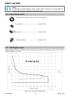
21
20
A-11232
ON
OFF
22
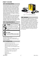
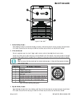
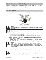
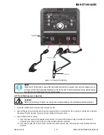
Figure 3-2: Rear Panel
1. Positive Welding Terminal
Positive Welding Terminal 2" (50mm) dinse. Welding current flows from the Power Source via heavy duty bayonet type terminals.
It is essential, however, that the male plug is inserted and turned securely to achieve a sound electrical connection.
2. 8 Pin Control Socket
The 8 pin receptacle is used to connect a trigger switch or remote control to the welding Power Source circuitry:
To make connections, align keyway, insert plug, and rotate threaded collar fully clockwise. The socket information is included
in the event the supplied cable is not suitable and it is necessary to wire a plug or cable to interface with the 8 pin receptacle.
NOTE!
When not using a Remote, disconnect any remote control device or it may limit the preview and actual
output current range.
Socket Pin
Part Number / Description
1
Not used
2
Trigger Switch Input
3
Trigger Switch Input
4
Not used
5
Remote Control 5k ohm Potentiometers Maximum
6
Remote Control 5k ohm Potentiometers Minimum
7
Remote Control 5k ohm Potentiometer Wiper
8
Not used
Table 3-2: 8 Pin Control Plug Configuration
3. Negative Welding Terminal
Negative Welding Terminal 50 mm dinse. Welding current flows from the Power Source via heavy duty bayonet type terminals.
It is essential, however, that the male plug is inserted and turned securely to achieve a sound electrical connection
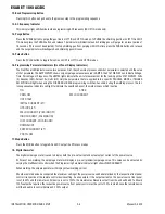
3
4
5
6
7
8
1
2
A-11228


