


ESAB ET 186i AC/DC
Manual 0-5425 3-15 INSTALLATION, OPERATION AND SETUP
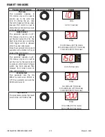
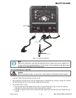
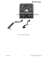
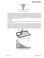
3.11 Short Circuit Protection While Welding
To prolong the useful life of a TIG tungsten electrode and eliminate tungsten contamination to welding point, the ET 186i AC/DC
incorporates special circuitry.
In all TIG processes, after the welding arc has established, if the tungsten electrode touches the work the current defaults to 33
amps. If the short exists for more than 1-2 seconds, the output is turned off.
In STICK mode, if the electrode touches the work for more than two seconds the welding current is reduced to 0 Amps.
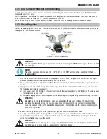
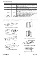
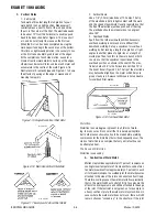
3.12 Victor Regulator
Pressure regulator (Figure 3-7) attached to the cylinder valve reduce high cylinder pressures to suitable low working pressures for
welding, cutting, and other applications.
LOW PRESSURE
GAUGE (DELIVERY)
HIGH PRESSURE
GAUGE (SUPPLY)
INLET
CONNECTION
OUTLET
CONNECTION
PRESSURE
ADJUSTING
SCREW
A-09414_AB
Figure 3-7: Victor CS Regulator
!
WARNING
Use the regulator for the gas and pressure for which it is designed. NEVER alter a regulator for use with
any other gas.
NOTE!
Regulators purchased with open 1/8", 1/4", 3/8", or 1/2" NPT ports must be assembled to their in-
tended system.
1. Note the maximum inlet pressure stamped on the regulator. DO NOT attach the regulator to a system that has a higher
pressure than the maximum rated pressure stamped on the regulator.
2. The regulator body will be stamped “IN" or “HP" at the inlet port. Attach the inlet port to the system supply pressure con-
nection.
3. If gauges are to be attached to the regulator and the regu lator is stamped and listed by a third party (i.e. “UL" or “ETL").
The following requirements must be met:
a) Inlet gauges over 1000 PSIG (6.87 mPa) shall conform with the requirements of UL 404, “Indicating Pressure Gauges
for Compressed Gas Service."
b) Low pressure gauges must be UL recognized for the class of regulator they are being used on according to UL252A.
!
WARNING
DO NOT
use a regulator that delivers pressure exceeding the pressure rating of the downstream
equipment unless pro visions are made to prevent over-pressurization (i.e. system relief valve). Make
sure the pressure rating of the down stream equipment is compatible with the maximum delivery pres-
sure of the regulator.
4. Be sure that the regulator has the correct pressure rating and gas service for the cylinder used.
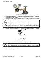
5. Carefully inspect the regulator for damaged threads, dirt, dust, grease, oil, or other flammable substances. Remove dust
and dirt with a clean cloth. Be sure the inlet swivel filter is clean and in place. Attach the regulator (Figure 3-9) to the
cylinder valve. Tighten securely with a wrench.
!
WARNING
DO NOT attach or use the regulator if oil, grease, flamma ble substances or damage is present! Have a
qualified repair technician clean the regulator or repair any damage.


