


ESAB ET 186i AC/DC
BASIC WELDING GUIDE 4-6 Manual 0-5425
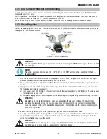
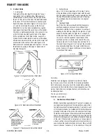
C. Vertical Welds
1. Vertical Up
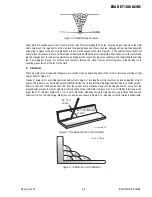
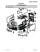
Tack weld a three feet length of angle iron to your
work bench in an upright position. Make yourself
comfortable on a seat in front of the job and strike
the arc in the corner of the fillet. The electrode needs
to be about 10º from the horizontal to enable a good
bead to be deposited. Refer Figure 4-15. Use a short
arc, and do not attempt to weave on the first run.
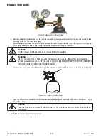
When the first run has been completed de-slag the
weld deposit and begin the second run at the bottom.
This time a slight weaving motion is necessary to cov-
er the first run and obtain good fusion at the edges.
At the completion of each side motion, pause for a
moment to allow weld metal to build up at the edges,
otherwise undercut will form and too much metal will
accumulate in the centre of the weld. Figure 4-16
illustrates multi-run technique and Figure 4-17 shows
the effects of pausing at the edge of weave and of
weaving too rapidly.
Art # A-07701
Figure 4-15: Single Run Vertical Fillet Weld
Art # A-07702
Figure 4-16: Multi Run Vertical Fillet Weld
Art # A-07703
Figure 4-17: Examples of Vertical Fillet Welds
2. Vertical Down
Use a 1/8" (3.2mm) electrode at 100 amps. The tip
of the electrode is held in light contact with the work
and the speed of downward travel is regulated so that
the tip of the electrode just keeps ahead of the slag.
The electrode should point upwards at an angle of
about 45º.
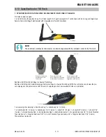
3. Overhead Welds
Apart from the rather awkward position necessary,
overhead welding is not much more difficult that
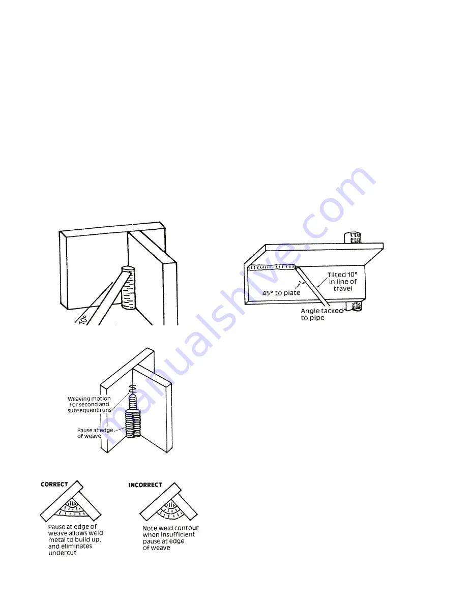
downhand welding. Set up a specimen for overhead
welding by first tacking a length of angle iron at right
angles to another piece of angle iron or a length of
waste pipe. Then tack this to the work bench or hold
in a vice so that the specimen is positioned in the
overhead position as shown in the sketch. The elec-
trode is held at 45º to the horizontal and tilted 10º in
the line of travel (Figure 4-18). The tip of the electrode
may be touched lightly on the metal, which helps to
give a steady run. A weave technique is not advisable
for overhead fillet welds.
Art # A-07704
Figure 4-18: Overhead Fillet Weld
Distortion
Distortion in some degree is present in all forms of weld-
ing. In many cases it is so small that it is barely perceptible,
but in other cases allowance has to be made before welding
commences for the distortion that will subsequently occur. The
study of distortion is so complex that only a brief outline can
be attempted hear.
The Cause of Distortion
Distortion is caused by:
A. Contraction of Weld Metal:
Molten steel shrinks approximately 11 per cent in volume on
cooling to room temperature. This means that a cube of mol-
ten metal would contract approximately 2.2 per cent in each
of its three dimensions. In a welded joint, the metal becomes
attached to the side of the joint and cannot contract freely.
Therefore, cooling causes the weld metal to flow plastically,
that is, the weld itself has to stretch if it is to overcome the
effect of shrinking volume and still be attached to the edge
of the joint. If the restraint is very great, as, for example, in
a heavy section of plate, the weld metal may crack. Even in
cases where the weld metal does not crack, there will still
remain stresses "Locked-up" in the structure. If the joint


