


Maintenance 12. Replacing the Control Board
C12 Rev.3
279
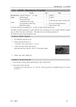
Installation: Control board 1
1.
Install the control board 1 protection plate.
Cross recessed head screws with captive washer: M3
×
6
Tightening torque: 0.45
±
0.1 N·m
Be careful of the assembly direction of the protection plate.
(See the photo)
2.
Install the control board 1 to the Arm #1.
Cross recessed head screws: 3-M3
×
8
Tightening torque: 0.45
±
0.1 N·m
Be careful not to drop the screws inside the Manipulator while
removing them.
3.
Connect the connector to the control board 1.
Connector: GS01
4.
Install the Arm #1 center cover.
For details, refer to
Maintenance: 3. Covers
.
5.
Check operation to see if the Manipulator's position and posture are out of position.
Move the Manipulator to two or three points (poses) of the registered points.
6.
If the Manipulator is out of position, calibrate all the joints and axes.
For details, refer to
Maintenance: 16. Calibration.
NOTE
NOTE
Содержание C12 Series
Страница 1: ...Rev 3 EM204R4255F 6 Axis Robots C12 series MANIPULATOR MANUAL ...
Страница 2: ...Manipulator manual C12 series Rev 3 ...
Страница 8: ...vi C12 Rev 3 ...
Страница 14: ...Table of Contents xii C12 Rev 3 ...
Страница 16: ......
Страница 30: ...Setup Operation 2 Specifications 16 C12 Rev 3 2 4 Outer Dimensions Unit mm ...
Страница 83: ...Maintenance This volume contains maintenance procedures with safety precautions for C12 series Manipulators ...
Страница 84: ......
Страница 155: ...Maintenance 4 Cable Unit C12 Rev 3 141 4 2 Connector Pin Assignment 4 2 1 Signal Cable ...
Страница 156: ...Maintenance 4 Cable Unit 142 C12 Rev 3 ...
Страница 157: ...Maintenance 4 Cable Unit C12 Rev 3 143 ...
Страница 158: ...Maintenance 4 Cable Unit 144 C12 Rev 3 4 2 2 Power Cable ...
Страница 159: ...Maintenance 4 Cable Unit C12 Rev 3 145 ...