


Maintenance 5. Joint #1
186
C12 Rev.3
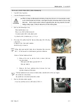
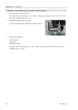
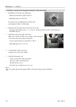
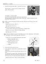
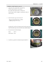
Installation: Joint #1 Electromagnetic brake (M/C Cable Downward)
1.
Install the Joint #1 brake to the brake plate.
Hexagon socket head cap bolts: 3-M4
×
25
Tightening torque: 4.0
±
0.2 N·m
Be careful of the assembly direction of the Joint #1
electromagnetic brake. (See the photo)
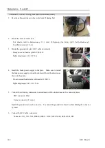
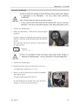
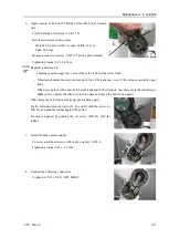
2.
Mount the Joint #1 brake plate to the Joint #1 motor unit.
For details, refer to
Maintenance: 5.1.1 Joint #1 - Replacing the Motor (M/C Cable Backward)
,
Installation step (4).
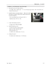
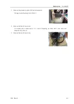
3.
Install the brake power supply to the plate.
Make sure to install the brake power supply so that the cables
will be in the direction as shown in the photo.
Cross recessed head screws with washer: 2-M3×6
Tightening torque: 0.45
±
0.1 N·m
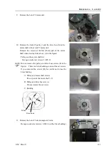
4.
Connect the M/C cable connectors.
Connector: X11, X010, BT1, BR011
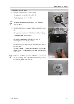
5.
Install the following covers.
Connector plate (M/C cable downward)
Base cover (M/C cable downward)
Base maintenance cover
For details, refer to
Maintenance: 3 Covers
.
If you disconnected the connector BT1 in the removal steps, perform calibration.
NOTE
Содержание C12 Series
Страница 1: ...Rev 3 EM204R4255F 6 Axis Robots C12 series MANIPULATOR MANUAL ...
Страница 2: ...Manipulator manual C12 series Rev 3 ...
Страница 8: ...vi C12 Rev 3 ...
Страница 14: ...Table of Contents xii C12 Rev 3 ...
Страница 16: ......
Страница 30: ...Setup Operation 2 Specifications 16 C12 Rev 3 2 4 Outer Dimensions Unit mm ...
Страница 83: ...Maintenance This volume contains maintenance procedures with safety precautions for C12 series Manipulators ...
Страница 84: ......
Страница 155: ...Maintenance 4 Cable Unit C12 Rev 3 141 4 2 Connector Pin Assignment 4 2 1 Signal Cable ...
Страница 156: ...Maintenance 4 Cable Unit 142 C12 Rev 3 ...
Страница 157: ...Maintenance 4 Cable Unit C12 Rev 3 143 ...
Страница 158: ...Maintenance 4 Cable Unit 144 C12 Rev 3 4 2 2 Power Cable ...
Страница 159: ...Maintenance 4 Cable Unit C12 Rev 3 145 ...