Maintenance 4. Cable Unit
C12 Rev.3
121
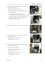
Leave out the other connector cables for a certain length, as shown in
the photo, in order to store them in the Arm #3.
7.
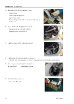
Pass the Ethernet cable, X052/X062 cable, and ground wire
(green/yellow) from the Arm #3 side to the Arm #4 side.
First pass the braid tube from the Arm #4 side to the Arm #3 side.
Insert the connectors through the braid tube, as shown in the photo, and
fix the tube with the wire tie so that connectors are not to be pulled out.
Then, pull the braid tube from the Arm #4 side while pushing the cables
from the Arm #3 side to pass the cables through.
(See the photo.)
8.
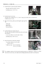
Pass the separated cable unit (Arm #4 side) from the Arm #4 to the Arm
#3.
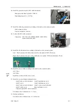
Silicone tube is provided. Leave out the silicone tube on the Arm #4
side.
Pass the following cables through the silicone tube: Ethernet cable,
X052/X062 cable, and ground wire (green/yellow) that have been
passed from the Arm #3 side.
Содержание C12 Series
Страница 1: ...Rev 3 EM204R4255F 6 Axis Robots C12 series MANIPULATOR MANUAL ...
Страница 2: ...Manipulator manual C12 series Rev 3 ...
Страница 8: ...vi C12 Rev 3 ...
Страница 14: ...Table of Contents xii C12 Rev 3 ...
Страница 16: ......
Страница 30: ...Setup Operation 2 Specifications 16 C12 Rev 3 2 4 Outer Dimensions Unit mm ...
Страница 83: ...Maintenance This volume contains maintenance procedures with safety precautions for C12 series Manipulators ...
Страница 84: ......
Страница 155: ...Maintenance 4 Cable Unit C12 Rev 3 141 4 2 Connector Pin Assignment 4 2 1 Signal Cable ...
Страница 156: ...Maintenance 4 Cable Unit 142 C12 Rev 3 ...
Страница 157: ...Maintenance 4 Cable Unit C12 Rev 3 143 ...
Страница 158: ...Maintenance 4 Cable Unit 144 C12 Rev 3 4 2 2 Power Cable ...
Страница 159: ...Maintenance 4 Cable Unit C12 Rev 3 145 ...


