


Maintenance 5. Joint #1
C12 Rev.3
159
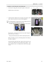
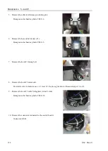
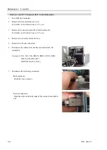
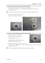
11.
Disconnect the internal cables from the base to the Arm #1 side.
Protect the connectors with masking tapes.
- To protect the connector’s clips
- To avoid adherence of cable grease
Disconnect the cables one by one in order from the smallest
connector to the largest one.
Do not attempt to pull all connectors at once.
Doing so may damage the cables.
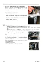
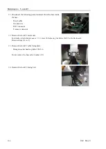
12.
Pull out the grease tube (between the base and the Arm #1) on
the Arm #1 side from the fitting.
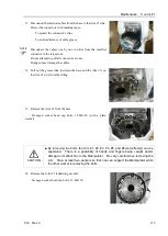
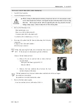
13.
Remove the Arm #1 from the base.
Hexagon socket head cap bolts: 15-M6
×
30 (with a plain
washer)
CAUTION
■
By removing the bolts, the Arm #1, #2, #3, #4, #5, and #6(end effector) can be
separated. There is a possibility of hands and fingers being caught and/or
damage or malfunction to the Manipulator. Be very careful when removing the
arm. Have at least two workers so that one can support the Manipulator while
the other worker is removing the bolts.
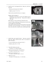
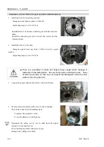
14.
Remove the Joint #1 reduction gear unit.
Hexagon socket head cap bolts: 12-M6
×
50
NOTE
Содержание C12 Series
Страница 1: ...Rev 3 EM204R4255F 6 Axis Robots C12 series MANIPULATOR MANUAL ...
Страница 2: ...Manipulator manual C12 series Rev 3 ...
Страница 8: ...vi C12 Rev 3 ...
Страница 14: ...Table of Contents xii C12 Rev 3 ...
Страница 16: ......
Страница 30: ...Setup Operation 2 Specifications 16 C12 Rev 3 2 4 Outer Dimensions Unit mm ...
Страница 83: ...Maintenance This volume contains maintenance procedures with safety precautions for C12 series Manipulators ...
Страница 84: ......
Страница 155: ...Maintenance 4 Cable Unit C12 Rev 3 141 4 2 Connector Pin Assignment 4 2 1 Signal Cable ...
Страница 156: ...Maintenance 4 Cable Unit 142 C12 Rev 3 ...
Страница 157: ...Maintenance 4 Cable Unit C12 Rev 3 143 ...
Страница 158: ...Maintenance 4 Cable Unit 144 C12 Rev 3 4 2 2 Power Cable ...
Страница 159: ...Maintenance 4 Cable Unit C12 Rev 3 145 ...