


Maintenance 6. Joint #2
204
C12 Rev.3
6.3 Joint #2 - Replacing the Timing Belt
Name
Qty.
Note
Maintenance
Parts
Timing belt (Joint #2) 540 mm
1
1655927
Belt tensile jig *
1
1674582
Tools
Hexagonal wrench
(width across flats: 4 mm)
1
For M5 hexagon socket head cap bolt
Cross-point screwdriver
1
For cross recessed head screws
Torque wrench
1
For tightening torque control
Cloth (cushioning)
1
For pressing arms
Belt tension meter
1
Refer: Unitta U-505
* The belt tensile jig is an assembly jig. Use the jig when adjusting belt tension.
The brake is mounted on each joint to prevent the arm from lowering due to its own weight while the
Controller power is OFF or the motor is OFF status. The brake does not work during replacement. Be
careful when performing maintenance work.
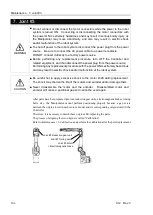
When removing the Joint #2 motor, tilt the Arm #2 and press it against the Arm #1.
Reference:
Maintenance: 6.1 Joint #2 - Replacing the Motor,
Removal step (2)
When pressing the arm, put a piece of cloth or a similar material between the arms to avoid contacting each
other. This protects the arm surfaces from scratching and paint peeling off.
Removal: Joint #2 Timing belt
1.
Follow Removal steps (1) through (4) of
Maintenance: 6.1 Joint #2 – Replacing the Motor.
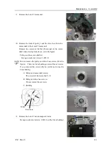
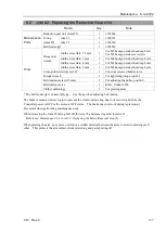
2.
Loosen the Joint #2 motor unit set screws.
Hexagon socket head cap bolts: 3-M5×25
(with a plain washer)
3.
Remove the Joint #2 timing belt.
Installation: Joint #2 Timing belt
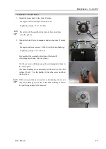
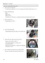
1.
Pass the Joint #2 timing belt around the pulley 1 and the pulley 2 of the Joint #2.
Pass the timing belt to the pulley 2 first, then, place it to the pulley 1.
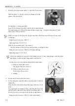
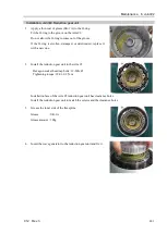
2.
Secure the Joint #2 motor unit.
For details, refer to
Maintenance: 6.1 Joint #2 – Replacing the Motor
,
Installation steps (5) to (6) and (10) to (11).
Содержание C12 Series
Страница 1: ...Rev 3 EM204R4255F 6 Axis Robots C12 series MANIPULATOR MANUAL ...
Страница 2: ...Manipulator manual C12 series Rev 3 ...
Страница 8: ...vi C12 Rev 3 ...
Страница 14: ...Table of Contents xii C12 Rev 3 ...
Страница 16: ......
Страница 30: ...Setup Operation 2 Specifications 16 C12 Rev 3 2 4 Outer Dimensions Unit mm ...
Страница 83: ...Maintenance This volume contains maintenance procedures with safety precautions for C12 series Manipulators ...
Страница 84: ......
Страница 155: ...Maintenance 4 Cable Unit C12 Rev 3 141 4 2 Connector Pin Assignment 4 2 1 Signal Cable ...
Страница 156: ...Maintenance 4 Cable Unit 142 C12 Rev 3 ...
Страница 157: ...Maintenance 4 Cable Unit C12 Rev 3 143 ...
Страница 158: ...Maintenance 4 Cable Unit 144 C12 Rev 3 4 2 2 Power Cable ...
Страница 159: ...Maintenance 4 Cable Unit C12 Rev 3 145 ...