Software Release: [App: 02.09.10039.00; Config: 2.9.20024; Built in PowerVision Configuration Studio Version:
2.9.23042; BTL: 02.09.10015.00]
Section 40
15
00-02-0996
2019-06-13
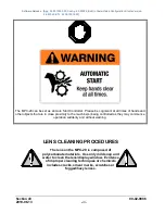
The operator must press the green start key to activate the auto start sequence. The red stop key will initiate
the auto stop sequence in the controller.
Two Contact Maintained Start/Stop (commonly known as Floats)
The Two Contact Maintained Start occurs when both contacts are active for an auto start and both contacts
are inactive for an auto stop (not momentarily). Depending on whether the application is emptying or filling,
the start float will need to be positioned above the stop float or below the stop float. It requires two digital
inputs, one for start and one for stop.
Two Contact Momentary Start/Stop
The Two Contact Momentary Start occurs when the start input is active momentarily for an auto start, and the
stop contact is momentarily active for an auto stop. The start/stop inputs may have start and stop timer
associated. Check this area in the Advanced Engine Settings under Timers. It requires two digital inputs, one
for start and one for stop.
(Pressure, Level, Flow or Temperature) Transducer Start/Stop
A transducer is needed for any of these auto start/stop types and setup in the Input/Output menu under Analog
Inputs. Set points for the desired auto start/stop type selected will be in populated menu in the application
configuration menu allowing the operator to enter the appropriate values needed in the application. Warnings
and shutdowns for any of these types are in the Advanced Engine Settings under Warnings and Shutdowns.
Auto Throttling Functions Defined
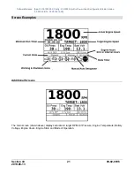
There are five automatic throttle functions in the MPC-20-R2 and are shown relative to the application chosen
as shown in the application configuration section. Each is detailed below:
Running Loaded Throttle
The Running Loaded Throttle function allows the controller, when in auto, to run the engine at a desired speed
between the minimum and maximum speed settings of the controller. This speed is set in the application
configuration menu when this throttle function is chosen.
(Pressure, Level or Flow) Transducer Throttle
A transducer is needed for any of these auto throttling functions and set up in the I/O menu. Set points for the
desired auto throttling function selected will be in populated menu in the application configuration menu
allowing the operator to enter the appropriate values needed to maintain a pressure, level, or flow in the
application. Warnings and shutdowns for any of these types are in the Advanced Engine Settings under
Warnings and Shutdowns.
Local Throttle Input
The Local Throttle Input throttles the engine between the minimum and maximum RPM set points when using
the 0-5V analog input function.
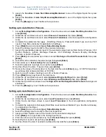
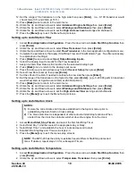
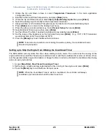
Quick-Start Setup Guide
The following sections provide a walk-through of the steps necessary for some of the various configurations
and settings available on the MPC-20-R2 Controller.
Cycling power to the controller is recommended
after making changes to set points.


