5.Description of Function Codes
EM15 User's Manual
78
on the difference between the feedback signal and the target signal, it adjusts the output frequency and constitutes
a feedback system to stabilize the controlled counter around the target value.
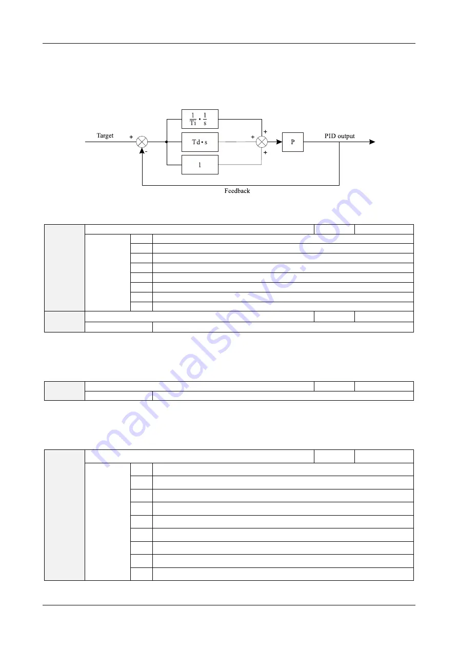
It is applied to process control such as flow control, pressure control and temperature control. The following
figure shows the principle block diagram of PID control.
Diagram 5-25 Principle block diagram of PID control.
C0-00
PID setting source
Default
7
Setting
Range
0
C0-01
1
AI1
2
AI2
3
AI3
4
Pulse setting (HDI)
5
Communication setting
6
Multi-function
7
New mode(Pressure Mode)
C0-01
PID digital setting
Default
50.0%
Setting Range
0.0%~100.0%
C0-00 is used to select the channel of target process PID setting. The PID setting is a relative value and ranges
from 0.0% to 100.0%. The PID feedback is also a relative value. The purpose of PID control is to make the PID
setting and PID feedback equal.
C0-02
PID setting changing time
Default
0.00s
Setting Range
0.00s~650.00s
The PID setting changing time indicates the time required for PID setting changing from 0.0% to 100.0%. The
PID setting changes linearly according to the changing time, reducing the impact caused by sudden setting change
on the system.
C0-03
PID feedback source
Default
0
Setting
Range
0
AI1
1
AI2
2
AI3
3
AI1 – AI2
4
Pulse setting (HDI)
5
Communication setting
6
AI1 + AI2
7
MAX (|AI1|, |AI2|)
8
MIN (|AI1|, |AI2|)
This parameter is used to select the feedback signal channel of process PID. The PID feedback is a relative value


