E300 Installation and Commissioning Guide
49
Issue Number: 1
Table 4-4 Isolated serial comms lead details
The “isolated serial communications” lead has reinforced insulation as
defined in IEC60950 for altitudes up to 3,000 m.
4.4.2 2 wire EIA-RS485 network
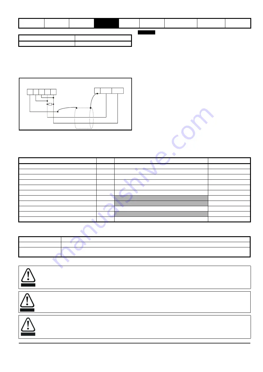
The diagram below shows the connections required for a 2 wire EIA-
RS485 network, using a master controller with an EIA-RS485 port.
Figure 4-11 2 wire EIA-RS485 network connections
If more than one drive is connected to a host computer / PLC etc, each
drive must have a unique serial address see
Any number in the permitted range 1 to 247 may be used.
4.4.3 Routing of the cable
A data communications cable should not run parallel to any power
cables, especially ones that connect drives to motors. If parallel runs are
unavoidable, ensure a minimum spacing of 300 mm (1 ft) between the
communications cable and the power cable.
Cables crossing one another at right-angles are unlikely to give trouble.
4.4.4 Termination
Termination resistors should not be required unless the baud rate is set
at or higher than 38.4 k Baud. Linking pins 1 and 8 of the drive
communications port connects an internal 120
Ω
termination resistor
between RXTX and RX\TX\. A resistor should also be connected at the
controller end of the cable.
4.5 Control connections
4.5.1
E300 Advanced Elevator
drive control connections
Table 4-5 The control connections consist of:
* Analog inputs can configured and used as digital inputs.
Key
:
All analog and digital terminal functions (including the relay) can be programmed in Menu F, Hardware I/O.
Part number
Description
4500-0096
CT USB Comms cable
Slave
0V
/TxRx
TxRx
3
7
2
0V /Rx Rx /Tx Tx
1
2
3
4
5
Master
termination resistor
E300
NOTE
Function
Qty
Control parameters available
Terminal number
Differential analog input *
1
Mode, offset, invert, scaling
5, 6
Single ended analog input *
2
Mode, offset, invert, scaling, destination
7, 8
Analog output
2
Source, scaling
9, 10
Digital input
3
Destination, invert, logic select
27, 28, 29
Digital input / output
3
Input / output mode, destination / source, invert, logic
24, 25, 26
Relay
1
Source, invert
41, 42
Safe Torque Off (STO), Drive enable
1
31
+10 V User output
1
4
+24 V User output
1
Source, invert
22
0V common
6
1, 3, 11, 21, 23, 30
+24 V External input
1
Destination, invert
2
Destination parameter:
Indicates the parameter which is being controlled by the terminal / function
Source parameter:
Indicates the parameter being output by the terminal
Mode parameter:
Analog - indicates the mode of operation of the terminal, i.e. voltage 0 - 24 V, current 4 - 20 mA etc.
Digital - indicates the mode of operation of the terminal, i.e. positive / negative logic
The control circuits are isolated from the power circuits in the drive by basic insulation (single insulation) only. The installer must ensure
that the external control circuits are insulated from human contact by at least one layer of insulation (supplementary insulation) rated for
use at the AC supply voltage.
If the control circuits are to be connected to other circuits classified as Safety Extra Low Voltage (SELV) (e.g. to a personal computer), an
additional isolating barrier must be included in order to maintain the SELV classification.
If any of the digital inputs (including the drive enable input) are connected in parallel with an inductive load (i.e. contactor or motor brake)
then suitable suppression (i.e. diode or varistor) should be used on the coil of the load. If no suppression is used then over voltage spikes
can cause damage to the digital inputs and outputs on the drive.
WARNING
WARNING
CAUTION
Содержание E300 Series
Страница 211: ......
Страница 212: ...0479 0005 01 ...


