150
E300 Installation and Commissioning Guide
Issue Number: 1
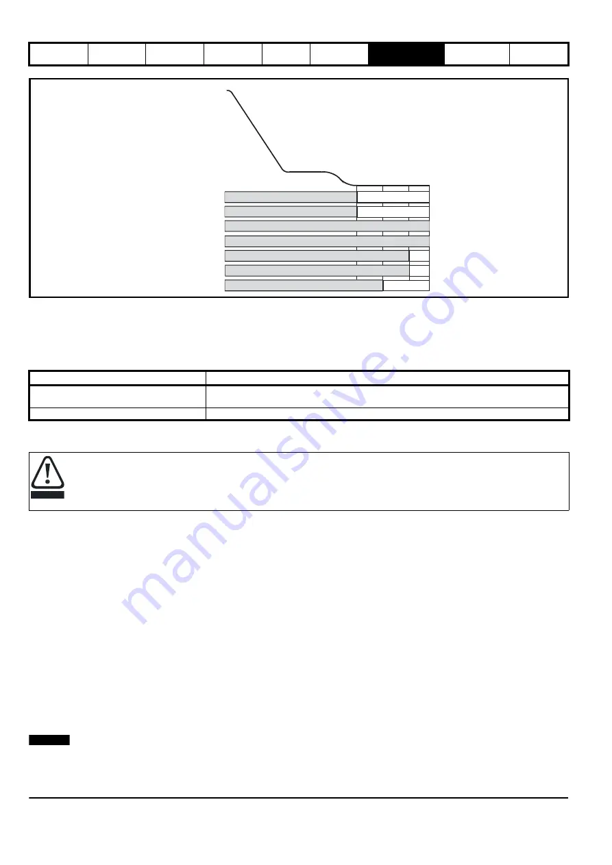
Figure 7-16 Brake control - Closed loop apply
7.9.3 Stop profile, motor contactor control
Following completion of the travel and during the stop sequence the motor brake is applied, after which the symmetrical current limit is ramped down
and the output motor contactors are opened. During the opening of the output motor contactors, the drive’s output should be inactive to avoid
potential damage to both the output motor contactors and the drive as a result of arcing.
Where
Motor Contactor Measured Delay Time
(
B32
) is < 50 ms the brake control in
Brake Control Apply Delay
(
D05
) should be increased.
Table 7-25 Motor contactor control parameters
7.10 Additional control functions
Additional features can be configured for the
E300 Advanced Elevator
drive as described below where these features are not enabled by default.
When selected, some additional features will require control inputs/outputs on the drive to be allocated. Where additional control inputs/outputs are
not available, this will require an additional SI-I/O option module to be installed.
The following additional control functions available on the
E300 Advanced Elevator
drive are covered in this section
•
Motor contactor control
•
Load cell compensation
•
Fast stop
•
Load measurement
•
Inertia compensation
•
Simulated encoder output
•
Advanced door opening
•
Emergency backup operation
•
Peak curve
•
Floor sensor correction
•
Short floor landing
•
Fast start
7.11 Motor contactor control
The output motor contactor control can be implemented on either the Elevator controller or the drive. The
E300 Advanced Elevator
drive has output
motor contactor control which can be enabled and routed to any digital output, by default this control is not enabled.
N
The
E300 Advanced Elevator
drive can be used in Elevator applications with zero output motor contactors and has TUV Nord approval to EN81. For
further details contact the supplier of the drive.
Parameter
Detail
Motor Contactor Measured Delay Time
(
B32
)
Measured time between the end of the travel and the time taken to fully close the output motor
contactors, and remove the Safe Torque Off (STO), Drive enable, value should be > 50 ms
Brake Control Apply Delay
(
D05
)
Brake apply delay, increase where
Motor Contactor Measured Delay Time
(
B32
) is < 50 ms
Motor contactor
STO, Drive enable
Creep speed
Deflux
motor
Motor
contactor
delay
Speed loop Run Kp
Direction selected
Speed loop Run Ki
Brake control
Brake Control Output
(
)
D03
External
motor
contactor
control
(
)
Creep Stop Jerk
G18
()
Brake
Control
Apply
Delay
D05
Creep Stop Deceleration Rate
(
)
G17
Run Speed Loop P Gain
(
)
I06
Run Speed Loop I Gain
(
)
I07
The brake control must be adjusted by a responsible person who is familiar with the system operation and safety requirements to avoid a
safety hazard. Correct adjustment should be carried out as detailed in this
Installation and Commissioning Guide
to avoid the risk of
product damage or a safety hazard.
CAUTION
NOTE
Содержание E300 Series
Страница 211: ......
Страница 212: ...0479 0005 01 ...


