E300 Installation and Commissioning Guide
143
Issue Number: 1
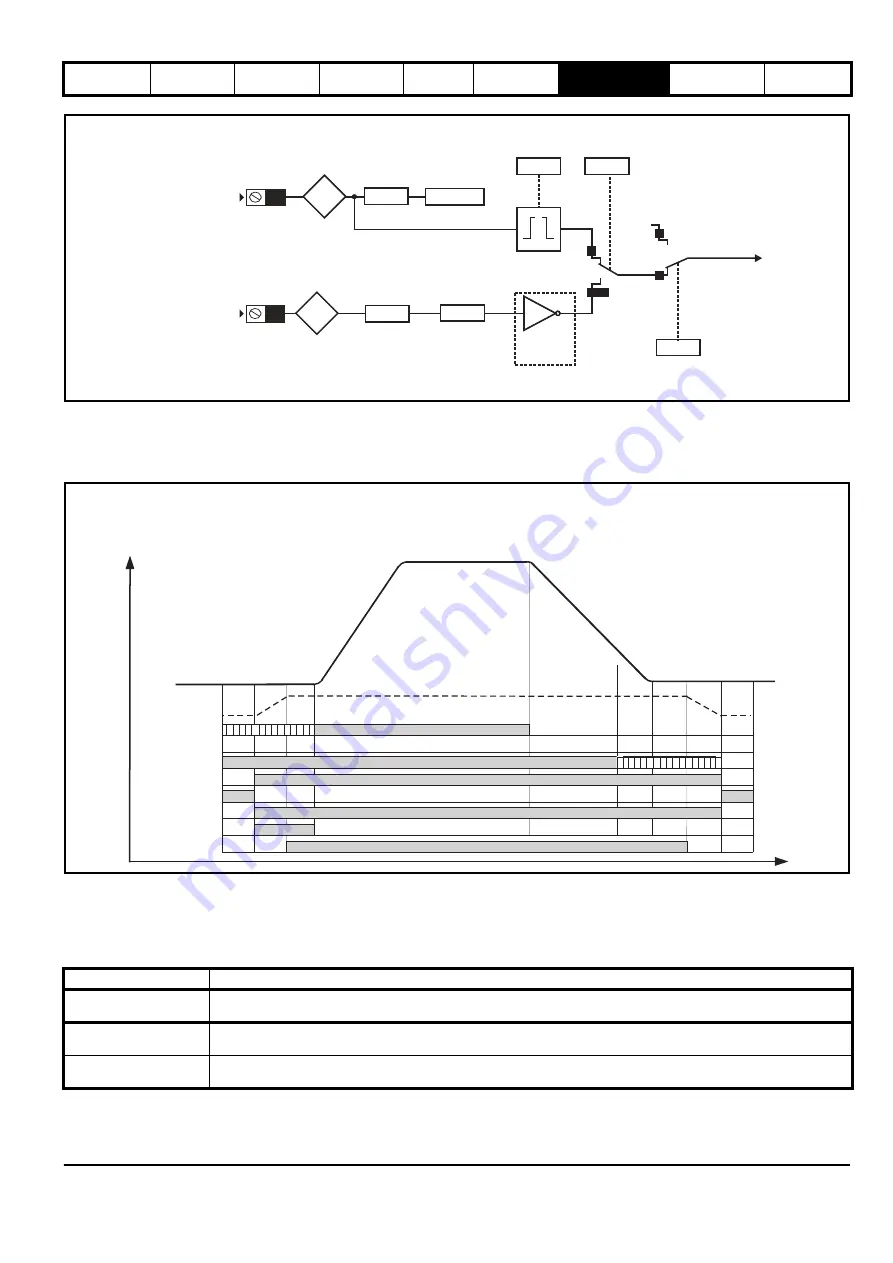
Figure 7-6 Stop signal for Direct to floor
Direct to floor operation utilizes a feature of digital input 4, which bypasses the normal input logic resulting in a fast response to a change in the input
signal, such that when the sensor is activated the signal is sampled in <1 µs. When digital input 4 is used for the Direct to floor slowing signal, it is
recommended that the input is not used for any other purpose and
Digital Input 4 Destination
(
F21
) should be set to a value of 'A00'. It is possible to
specify whether the positive or negative edge of the floor sensor correction signal is detected using
Direct To Floor Edge Detection
(
H10
).
Figure 7-7 Direct to floor profile, timing diagram
7.7 Creep to floor / Direct to floor - Start
For geared and gearless Elevator applications operating in Creep to floor mode / Direct to floor mode, the start performance can be optimized using
the following procedure. For open loop operation only the start optimizer is available.
Table 7-15 Start set-up control
7.7.1 Start lock on brake release control
The start lock uses a position controller for the start and can be used to prevent roll back on brake release. The start lock holds the Elevator car in
position following Drive enable and opening of the brake. Once the profile is started the start lock position control is disabled.
Feature
Details
Speed control loop gains
For Closed loop operation the Start Speed Loop P Gain (
I01
) and Start Speed Loop I Gain (
I02
) gains can be used for
optimization
Start lock
A start lock position control is available for Closed loop operation and used in addition to the start speed loop gains. This
control is mainly used in gearless applications where high start speed loop gains may not possible.
Start optimizer
The start optimizer is available for both Open and Closed loop operation with either geared or gearless Elevators. The
start optimizer is mainly used to overcome mechanical imperfections in the system.
Digital
Input 4
Digital
Input Y
Loss Of
Speed
Signals
Digital
Input Y
Invert
Digital
Input Y
Destination
Digital
Input Y
State
Digital
Input 4
Invert
Digital
Input 4
Destination
Direct To Floor
Edge Detection
Elevator
Control
Mode
Stop signal
Digital
Input 4
State
T27
F15
H10
H09
H19
F21=A00
F06
Txx
1
0 or 2
0
1
Stop signal
Direct To Floor
Sensor
Mode
Creep
To Floor
Direct
To
Floor
Any Speed signal
Drive active
Direction
FAST disable
STO, Drive enable
Start lock
Speed selection
Torque producing current
Debounce
motor
contac
tors
(100
ms)
Brake
Control
Apply
Delay
(
)
D05
Interlock
delay
(>
50
ms)
Control terminal 26
Run Jerk 1
(
)
G13
Run Jerk 2
(
)
G14
V1 Speed Reference
(
)
G01
V10
(
)
G10
Speed Reference
Ramp
torque
(100
ms)
Ramp
torque
(100
ms)
Control terminal 7 (V2), 26 (V3), 5 (V4)
Control terminal 28
Control terminal 31
Drive active, L06
Brake output
Control terminal 25
Start lock position Kp, 120
External
motor
contactor
control
External
motor
contactor
control
Run Jerk 3
(
)
G15
Brake
Control
Release
Delay
()
D04
Acceleration Rate
(
)
G11
Deceleration Rate
(
)
G12
Run Jerk 4
(
)
G16
Brake Control Apply Delay
(
)
D05
Содержание E300 Series
Страница 211: ......
Страница 212: ...0479 0005 01 ...


