118
E300 Installation and Commissioning Guide
Issue Number: 1
A16
(
Position Feedback Phase Angle
C13
)
RFC-S mode Position feedback phase angle
. The phase angle between the rotor flux and the encoder feedback position must be set-up correctly
for the drive to control the motor correctly. If the phase angle is known it can be manually entered by the user. Alternatively the drive can automatically
measure the phase angle by performing a phasing test (see
A26
Motor Autotune
B11
). When the phasing test is complete, the new position feedback
phase angle value will be automatically updated in this parameter. Following the phasing test, the position feedback phase angle value and can be
modified if required and will become effective immediately. The position feedback phase angle has a factory default value of 0.0, but this is not
affected when defaults are loaded by the user.
A16
(
Slip Compensation Enable
B10
)
Open loop mode Slip compensation enable
.
A21
(
B06
) and
A19
(
B03
) define the frequency to
voltage characteristic applied to the motor.
A21
(
B06
),
A22
(
B07
) and
A20
(
B05
)
Motor number of poles are used to calculate the rated slip of the motor for slip compensation.
Rated slip (Hz) = Motor Rated Frequency - (Motor pole pairs x Motor rated speed / 60)
If slip compensation is required
A22
(
Motor Rated Speed
B07
) should be set to the motor nameplate value, which should give the correct
compensation for a hot motor provided the nameplate value is correct. Slip compensation can be used throughout the speed range of the motor, i.e.
below base speed and in the flux weakening region, to correct / minimise a change of motor speed with load.
Slip compensation is disabled under the following conditions:
1.
A22
B07
) = 0
2.
A22
B07
) =
A21
(
B06
) x 60 / Pole pairs, i.e. synchronous speed.
3.
A16
(
Slip Compensation Enable
B10
) = Off (0).
A17
(
Drive Encoder Feedback Reverse
C12
)
RFC-A and RFC-S mode: Drive Encoder Feedback Reverse.
If encoder feedback invert parameter = On (1) the encoder feedback position from
the motor is rotated within the drive, this can be used to reverse the direction of the encoder feedback where incorrect wiring connections have been
made to either the drive or encoder.
(
Low Frequency Voltage Boost
B12
)
Open loop mode: Low Frequency Voltage Boost.
The default value for the low frequency voltage boost depends on the frame size of the drive
being used as follows:
3.0 % up to frame size 6 drives
2.0 % for frame size 7 drives
Refer to
A23
(
Open Loop Control Mode
B09
) for more details.
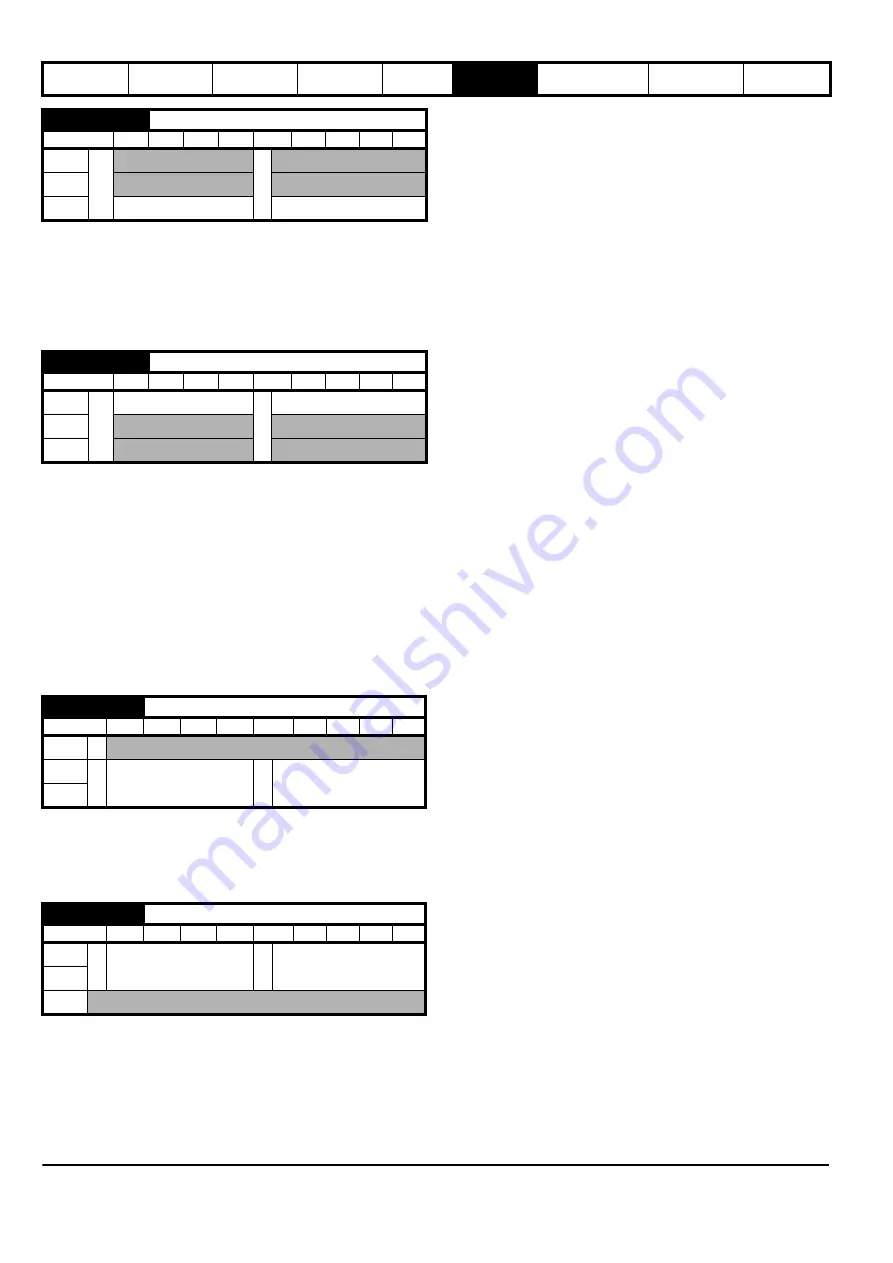
A16 {C13}
Position Feedback Phase Angle
RW
Num
ND
US
OL
Ú
Ö
RFC-A
RFC-S
0.0 to 359.9
°
0.0
°
A16 {B10}
Slip Compensation Enable
RW
Bit
US
OL
Ú
Off (0) On (1)
Ö
On (1)
RFC-A
RFC-S
A17 {C12}
Drive Encoder Feedback Reverse
RW
Bit
US
OL
RFC-A
Ú
Off (0) On (1)
Ö
Off (0)
RFC-S
A17 {B12}
Low Frequency Voltage Boost
RW
Num
US
OL
Ú
0.0 to 25.0 %
Ö
3.0 %
RFC-A
RFC-S
Содержание E300 Series
Страница 211: ......
Страница 212: ...0479 0005 01 ...


