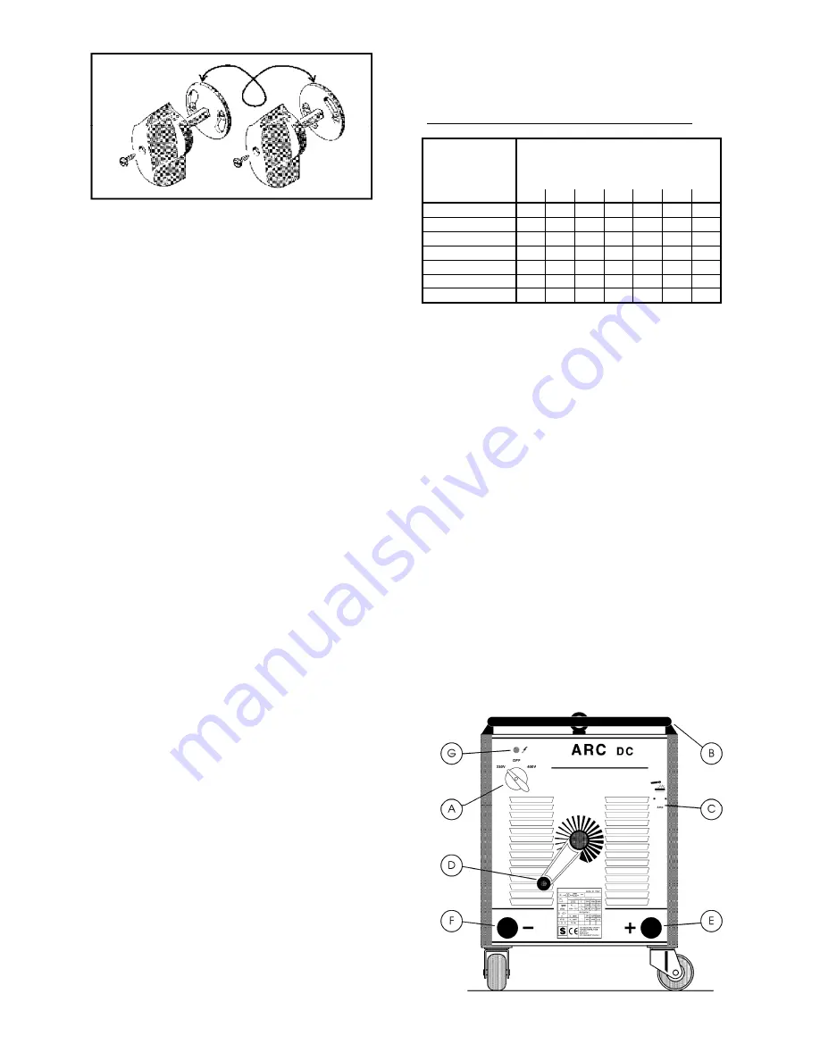
background image


Connect supply cable : the yellow-green wire of cable 
must be connected to an efficient earth point of the 
system, the remaining wires should be connected to the 
feed line through an isolation switch placed, if possible, 
close to the working area so as to switch the unit off 
quickly if necessary.  


6

The magnetothermic switch capacity or of fuses in series 
with switch should be equal or above the current 

I

1


absorbed is known


by reading the


technical specifications 

on the


unit i.e. feed voltage U

 available.  

Any extensions should have adequate sections for current 
absorbed 

I

1

 
2.3 OUTPUT CONNECTIONS 
 
2.3.1 Connecting the electrode holder 

  The electrode holder must be connected to the machine 

in compliance with the polarity indicated on the box of 
electrodes that you are going to use. 


 When you connect the electrode holder cable and the 

hearth cable, make sure that the power cable terminals 
are well tightened.


  The jaws of the electrode holder must be kept tightened 

and the surfaces must be kept in good condition to ensure 
good contact with the electrode rod.


 Defective jaws will allow the electrodes to move which 

will make welding difficult.


  The connection between the electrode holder cable and 

the electrode holder must be well tightened.


  Use well insulated electrode holders.


 Never touch the electrode holders of two different 

welding machines at the same time.


  Always avoid contact between parts of the body and the 

electrode holder and/or the electrode.


2.3.2 Connecting the Earth Clamp 

 Make sure that the earth clamp makes good contact 

with the workpiece.


  Check that the earth cable is tightly fitted to earth clamp; 

periodically check to make sure that this connection 
remains well tightened.


A poorly tightened connection can cause current drops 
during welding and also cause overheating of the earth 
clamp and cable which can create the danger of burns. 

 The weld circuit must not be purposefully placed in 

direct or indirect contact with the protection lead if not in 
the workpiece. 

  If the workpiece is intentionally connected to the system 

earth by means of a protection lead, the connection has to 
be as direct as possible and done with a lead that has a 
cross section at least equal to that of the welding current 
return cable. 
A second earth clamp, placed in the immediate vicinity, 
can also be used. 
 

2.3.3 Choosing the right welding cables 

We recommend using the shortest possible welding 
cables type H01 N2-D or H01 N2-E, in compliance with 
CENELEC HD22.6 S1. 

Too much resistance in the welding cables can reduce the 
output available for the welding. 
The performance of any arc welding machine depends, 
generally, on the condition of the cables and the cable 
connections. 
 
CROSS SECTIONS OF WELDING CABLES IN mm

2


WELDING 

CURRENT IN 

AMPERE


DISTANCE IN METRES FROM THE 

MACHINE 


15

20 30 40 45

50

60

100 

35

35 35 50 50

50

50

150 

35

35 50 50 70

70

90

200 

35

50 50 70 70

95

100

250 

35

50 70 70 95

100 150

300 

50

70 70 95 100 150 150

350 

50

70 95 100 

150 150 200

400 

50

95 95 150 

150 200 210

 
NOTE: The cross sections listed in the table are those for 
each single conductor (electrode holder or ground clamp). 
The cross sections listed in the table are those for each 
single conductor (electrode holder or group clamp). 
The cross sections of the cables can be obtained by 
connecting in parallel 2 or 3 conductors having the same 
cross section. For example : 
150mm

2

=three 50mm

2

 cables linked together in parallel. 

200mm

2

=2x95 mm

2

 cables or 3x70 mm

2

 cables linked 

together in parallel. 
 

2.3.4 Connecting two welding machines in parallel 

Two welding machines can be connected in parallel so that 
one obtains on output current greater than the  output 
current of each single machine. 
It is important that the positive pole of one machine is 
connected to the positive pole of the other machine and 
likewise that the negative pole of one machine is connected 
to the negative pole of the other machine. 
When making this connections it is important to abide by the 
cross sections shown in the table.  
After having connected two machines in parallel, set the 
output current of each machine to the halfway point so that 
each machine will produce half of its maximum output 
current.  
This is recommended in order to balance the heath 
produced by each machine, thus allowing the operator to 
make the best use of duty cycles of both machines. 
 

3 PANELS DESCRIPTION 


Содержание MMA 793

Страница 1: ...TRUCTIONS POUR POSTES A SOUDER A L ARC Pag 11 E MANUAL DE INSTRUCCIONES PARA SOLDADORAS DE ARCO Pag 14 P MANUAL DE INSTRU ES PARA SOLDADORES COM ARCO Pag 17 Parti di ricambio e schema elettrico Spare...

Страница 2: ...are l articolo ed il numero di matricola Tutti i collegamenti devono essere eseguiti in conformit alle vigenti norme e nel pieno rispetto della legge antinfortunistica Vedi norma CEI 26 10 CENELEC HD4...

Страница 3: ...atura non deve essere posto deliberatamente a contatto diretto o indiretto con il conduttore di protezione se non nel pezzo da saldare Se il pezzo in lavorazione viene collegato deliberatamente a terr...

Страница 4: ...completo Trasformatore di potenza in corto circuito C Indice di regolazione Raddrizzatore in corto circuito Indica la corrente di saldatura a cui regolata la macchina Corrente di saldatura instabile o...

Страница 5: ...Duty Cycle Percentage The duty cycle is the number of minutes expressed as a percentage the machine can operate arc on within a ten minute period without overheating I2 Output welding current U2 Secon...

Страница 6: ...a protection lead the connection has to be as direct as possible and done with a lead that has a cross section at least equal to that of the welding current return cable A second earth clamp placed in...

Страница 7: ...ower supply Keep the welding cables the electrode holder and the earth clamp in good condition Periodically clean inside the machine blowing dust and dirt away from internal components with a light je...

Страница 8: ...d die Seriennummer angeben Alle Anschl sse m ssen in bereinstimmung mit den geltenden Normen und unter strenger Beachtung der geltenden Unfallverh tungsvorschriften siehe Norm CENELEC HD 4277 ausgef h...

Страница 9: ...omabfall berhitzung des Kabels und der Masseklemme mit folglicher Verbrennungsgefahr f hren Keinen direkten oder indirekten Kontakt zwischen Schwei stromkreis und Schutzleiter herstellen es sei denn a...

Страница 10: ...den Vor Arbeiten im Inneren der Maschine die Schwei maschine ausschalten und den Netzstecker ziehen Auf den einwandfreien Zustand der Schwei kabel des Elektrodenklemmhalters und der Massklemme achten...

Страница 11: ...1 NE doit PAS tre utilis e pour le soul vement dans des locaux a voir IEC 664 Si vous d sirez des informations suppl mentaires sur votre poste souder nous vous prions de pr ciser l article et son num...

Страница 12: ...e Veillez ce que le connecteur de masse fasse toujours un bon contact sur la pi ce souder Assurez v connecteur de masse Contr lez p riodiquement cette connexion Une jonction desserr e peut provoquer d...

Страница 13: ...c bles de soudage les lectrodes et le connecteur de masse soient toujours en bon tat Nettoyer p riodiquement la machine l int rieur liminer la poussi re existante avec un jet mod r d air sec MAUVAIS...

Страница 14: ...vestidos Adaptado para soldadura TIG U0 PEAK Tensi n al vac o secundaria Valor de pico X Factor de servicio porcentual El factor de servicio expresa el porcentaje de 10 minutos durante los cuales la s...

Страница 15: ...ldadura y recalentamientos excesivos del cable y del borne de masa con un peligro consiguiente de quemaduras El circuito de soldadura no se tiene que colocar deliberadamente en contacto indirecto con...

Страница 16: ...ables de soldadura la pinza portaelectrodo y el borne de masa en buenas condiciones Peri dicamente hay que limpiar el interior de la m quina Quitar el polvo acumulado con un moderado chorro de aire se...

Страница 17: ...orme as vigentes normas e no pleno respeito da lei ver norma CEI 26 10 CENELEC HD427 1 1 EXPLICA O DOS DADOS T CNICOS Montar as pe as correspondentes ao soldador Para levantar a m quina utilizar as du...

Страница 18: ...querimadura devido ao contacto acidental O circuito de soldadura n o deve ser posto deliberadamente em contacto directo ou indirecto com o condutor de protec o mas sim na pe a a soldar Se a pe a em tr...

Страница 19: ...manivela no sentido dos ponteiros do rel gio aumenta se a intensidade da corrente no sentido contr rio aos ponteioros do rel gio diminui se E Polo positivo F Polo negativo G L mpada piloto Indica que...

Страница 20: ...ULHO GUIA VIDE 36 APPOGGIO REST AUFLAGER APPUI APOYO APOIO 37 AVVOLGIMENTO PRIMARIO PRIMARY WINDING PRIM RWICKLUNG ENROULEMENT PRIMAIRE ARROLLAMIENTO PRIMARIO ENROLAMENTO PRIM RIO 38 AVVOLGIMENTO SECO...

Страница 21: ...Artt Items 793 794 795 798 799 21...

Страница 22: ...PORTE FUSIBLE PORTA FUSIBLE PORTA FUS VEL 29 VENTILATORE MOTOR FAN LUFTER MOTOVENTILATEUR VENTILADOR VENTILADOR 30 BOCCOLA ISOLANTE INSULATION ISOLIERUNG ISOLATION AISLAMIENTO ISOLAMENTO 31 RADDRIZZAT...

Страница 23: ...Art 796 797 23...

Страница 24: ...range Orange Nardnja Alaranjado I Rosa Pink Rosa Rose Rosa Rosa L Rosa nero Pink black Rosa schwarz Rose noir Rosa negro Rosa negro M Grigio viola Grey purple Grau violett Gris violet Gris violeta Cin...

Страница 25: ......

Страница 26: ...Cod 381656 10 2009...

Отзывы: