©2019 ECHO Incorporated. All Rights Reserved.
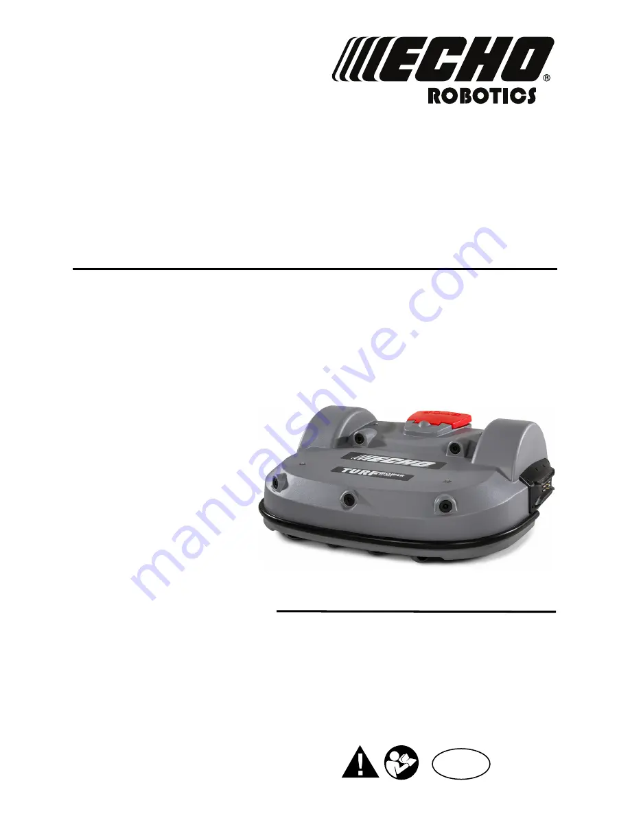
Technical Manual
Robotic Mower
TM-2000
EN
ENGLISH
P/N 99922205383
VERSION 1.0
05/28/2019
www.echorobotics.com
DRAFT
05-23-2019
Страница 1: ... 2019 ECHO Incorporated All Rights Reserved Technical Manual Robotic Mower TM 2000 EN ENGLISH P N 99922205383 VERSION 1 0 05 28 2019 www echorobotics com D R A F T 0 5 2 3 2 0 1 9 ...
Страница 2: ...ate 6 Inactive Modes 10 Chapter 6 Installation 10 Station Loop Wire Installation 11 Peripheral Wire Installation 11 Peripheral Wire Installation Offsets 12 Sites Containing Narrow Straits 13 Sites With Long Lanes 13 Obstacles 13 Islands 14 Water Obstacle 15 Sloped Fields 15 Configuration 16 Overlaps 17 Multi Field Peripheral Wire Installation 18 Configuration 18 Configuration Examples 20 Chapter 7...
Страница 3: ...ervice Procedures 58 Sonar Replacement 59 Bumper Replacement 59 Front Lift Cushion Replacement 59 Rear Lift Cushion Replacement 60 Front Wheel Replacement 60 Rear Wheel Replacement 60 Gear Motor Replacement 61 Battery Removal and Installation 62 Cutting Disk Service 63 Blade Replacement 63 Aluminum Anti friction Disc Replacement 64 Cutting Head Reassembly 64 Cutting Motor Service 65 Cutting Motor ...
Страница 4: ...ry and Housing 73 Lift Sensors 74 Wheels Motor and Gear Box 75 Cutting Head 76 Electrical Parts 77 Main Frame 78 Main Bars 79 Accessories 80 Cover and Chassis 81 Gear Motor Cutting Head and Front Wheel 83 Chapter 13 Specifications 84 Capacity 84 Cutting 84 Battery 84 Weight and Dimensions 84 Software and Monitoring 84 Intelligence 84 Safety 84 Dimensions 85 D R A F T 0 5 2 3 2 0 1 9 ...
Страница 5: ... the limits or a Class A digital device pursuant to part 15 of the FCC Rules These limits are designed to provide reasonable protection against harmful inter ference when the equipment is operated in a commer cial environment This equipment generates uses and can radiate radio frequency energy and if not installed and used in accordance with the instruction manual may cause harmful interference to...
Страница 6: ...ts the station loop wire it follows it to the charging station The station loop wire guides the robot into and out of the charging station Safety and Information Label Caution The robot can be dangerous if misused Never place hands or feet under the robot while operating Beware of projectiles Keep a safe distance Keep animals away from the robot Water cleaning with high pressure jet systems can ca...
Страница 7: ...ich will cause the robot to change direction when it touches an obstacle 8 Rear wheel 9 Charge contact Connects to the charging arm on the charging station 10 Cutting heads Equipped with three cutting blades 11 Li Ion Lithium Ion battery Supplies power to the robot 12 Electrical box Contains the electronics and the gear drive motors 13 Disc safety guard A protective guard which inhibits contact wi...
Страница 8: ...Numeric buttons Press to select menu choices and enter numeric values 2 LED screen Displays the current information 3 LED Indicates the user interface is switched ON 4 ON button Press to turn the user interface ON 5 Navigation buttons Press to highlight menu options 6 Back button Press to exit a menu and return to previous level 7 Accept button Press to accept an operation or setting 8 Service men...
Страница 9: ...d that is gener ated by the peripheral wire 4 1 7 Tilt Rollover and Temperature Sensors These sensors are located on the main circuit board inside of the electrical box The tilt sensor detects the angle of the slope on which the robot is mowing If this angle exceeds 30 58 an alarm will be raised and the robot will stop moving The rollover sensor detects if the robot has been tipped upside down or ...
Страница 10: ...al State Description Autonomous Mission State The robot operates in cycles in which it mows the grass or charges the battery Inactive State The robot can enter an inactive state if there is a condition that causes the Autonomous Mission State to stop The robot will return to the autonomous mission state when the problem has been resolved or when a specific command has been issued Service State Ini...
Страница 11: ...pattern until it senses that the grass is short It will then continue in normal operating mode When the robot contacts and obstacle it will maneuver away from it 5 1 2 Go To Charging Station Mode When working the robot checks the current conditions and its programmed instructions Examples are the battery needs to be charged programmed mowing time has ended for multi field installations this corres...
Страница 12: ...Field 1 peripheral wire and station loop wire overlap Next the robot follows the station loop wire until it docks at the charging station 5 1 3 Charge Mode In Charge Mode the robot will dock and remain in the charging station until the battery is fully charged The next operations that will be performed depend on programming and external conditions The robot will remain at the charging station if r...
Страница 13: ... Two Fields With Station Loop This configuration contains a peripheral wire for each field and one station loop wire Before leaving the charging station the robot will deter mine which field to start mowing This will depend on the defined mowing schedule for each field If the schedule dictates that a specific field must be mowed at this time the robot will start mowing in that field If there are n...
Страница 14: ...nd the alarm cleared by manual intervention it is manually switched ON The robot will leave the Standby mode when a command is issued It will then enter the Self Test Mode before recommencing any activity 5 2 3 Self Test Mode Whenever the robot has been in the Standby Mode it will perform a self test to check the integrity of the entire system including electronics sensors mechanics and software W...
Страница 15: ...eripheral wire Minimum peripheral wire length is 656 ft 200 m If this minimum length is not possible install an inductor in series with the peripheral wire See the ECHO Robotics Parts Catalog for inductor kit information Maximum peripheral wire length is 3937 ft 1 200 m Use a second charging station when total length of the peripheral wire including islands and pseudo islands exceeds 3 281 ft 1 00...
Страница 16: ... dimensional values shown apply when the Wire crossing distance parameter is at the default setting of 0 2 m Rough grass that does not need to be mowed Raised hard landscaping Hard landscaping level with grass NOTE A path that crosses the field to be mowed should be level with the grass Lawn level planting 1 Peripheral wire 1 Rough grass 2 Peripheral wire шϯ ϯ Ō шϭ ŵͿ шϵϬΣ ϭ ϭ 1 2 20 in 510 mm 1 T...
Страница 17: ...the peripheral wire is not detected the robot cannot return to the charging station to charge its battery If the length of the lane is less than 49 2 ft 15 m then the minimum distance between the peripheral wire must be greater than 32 8 ft 10 m 6 6 Obstacles Obstacles are objects that the robot must avoid Exam ples are trees flower beds swing sets climbing frames trampolines sidewalks walking pat...
Страница 18: ... around an object place the approach and return sides of the peripheral wire directly next to each other do not cross or twist the wire secure with tie straps at 0 4 in 10 mm incre ments Create a pseudo island when an obstacle is less than 16 4 ft 5 0 m from the peripheral wire 49 2 ft 15 0 m from the charging station 16 4 ft 5 0 m from another island or pseudo island Install the peripheral wire a...
Страница 19: ...If the charging station is located at Point A program the robot to return to it in a clockwise direction If the charging station is located at Point B program the robot to return to it in a counterclockwise direction 6 9 Sloped Fields The maximum slope on any part of the field must be less than or equal to 17 If a sloping part of the field is well away from the peripheral wire no specific programm...
Страница 20: ...Parcels then press Select the parcel associated with the LOOP wire 9 Select Return direction then press Choose whether you want the robot to return in a clock wise or counterclockwise direction 10 Disable the use of the trackborder Select Use trackborder and check the button OFF This ensures that when the robot is in this field it will just follow the wire to reach the station 11 Press twice to re...
Страница 21: ...verlap with its neighboring one Each pair of wires which overlap must be desig nated as neighboring fields Station loop wire 1 Field 1 is the small wire to which the charging station is connected In this example it overlaps the larger peripheral wires and fields When in this field the robot will not use the trackborder it will follow the station loop wire to enter the charging station All three fi...
Страница 22: ... 10 Select Connected to parcels and connect the station to the loop parcel 11 Select Station Inside Parcel s Wire and specify whether the station is on the inside or the outside of the station loop wire 6 13 2 Start Zones Start zones define where and how the robot starts mowing A start zone is defined for a parcel Multiple start zones can be defined for the same wire parcel The Start Zone screen d...
Страница 23: ... field it then takes the specified direction Distance Min Distance Max This is the distance that the robot will travel along the trackborder after leaving the station before starting mowing A random value between the minimum and maximum values will be selected Distance Min and Distance Max are measured from the point where the robot enters the parcel if this differs from the one in which the charg...
Страница 24: ...et the following parame ters Peripheral Wire Configuration 1 Press and hold 9 on the numeric keypad until the technician s menu appears 2 The TECHNICIAN SETTING menu will display Select 1 Infrastructure then press 3 The INFRASTRUCTURE menu will display Select 1 Peripheral wires then press 4 The WIRES SETTINGS menu will display Select 1 Wire CH0 then press 5 The WIRE CH0 NO SIGNAL menu will display...
Страница 25: ...ame Parcel 2 to Field After renaming select V located in the bottom row then press 6 The FIELD screen will display Select Use Track border then press 7 Scroll down to 8 Neighboring parcels then press 8 The NEIGHBORING PARCELS screen will display Select LOOP then press Select Confirm then press 9 The FIELD screen will display Press twice to return to the INFRASTRUCTURE screen Station Configuration ...
Страница 26: ... The VALIDATE screen will display Select OK then press 9 The WIRES SETTINGS menu will display Select Wire CH5 then press 10 The Wire CH5 No Signal screen will display Select the numeric option next to SIGNAL CHANNEL press or and set the value to 1 then press 11 Check the value shown at the top of the screen The value should be positive if it is not select Reverse phase then press 12 Press once the...
Страница 27: ...TURE screen Station Configuration 1 Select 3 Stations then press 2 Select 9 Create manual station then press 3 The VALIDATE screen will display Select OK then press 4 The Manual Station 1 screen will display Select Connected to parcels then press 5 The VALIDATE screen will display Select OK then press 6 The Connected Parcels screen will display The option for Wire CH0 will be highlighted Press to ...
Страница 28: ...l display Select OK then press 9 The WIRES SETTINGS menu will display Select Wire CH5 then press 10 The Wire CH5 No Signal screen will display Select the numeric option next to SIGNAL CHANNEL press or and set the value to 1 then press 11 Check the value shown at the top of the screen The value should be positive if it is not select Reverse phase then press 12 Press twice to return to the INFRASTRU...
Страница 29: ...y Set the Start Zone 2 values to 80 Set the Start Zone 3 value to 20 Select CONFIRM then press 18 The START ZONE screen will display Press four times to return to the INFRASTRUCTURE screen Station Configuration 1 Select 3 Stations then press 2 Select 9 Create manual station then press 3 The VALIDATE screen will display Select OK then press 4 The Manual Station 1 screen will display Select Connecte...
Страница 30: ...looding 7 2 The LCD Screen 7 3 The Actions Menu The operations provided in this menu depend on the current state of the robot when it is in the field and in the charging station 7 3 1 Operation In the Field Perform these operations when the robot is stopped and not in the charging station These operations would be performed if the robot has been stopped during its normal operation schedule or if i...
Страница 31: ... required command then press 4 Close the STOP button cover If the STOP button cover is not closed within 10 seconds the opera tion is canceled and will need to be repeated 7 4 The Settings Menu Use the options in this menu to control the operation of the robot 7 4 1 Schedule NOTE The schedule is based on a 24 hour clock Use this command to Define the weekly mowing schedule Define a schedule for ea...
Страница 32: ...at the process for all days and time periods required note The defined schedule can be copied to another day 10 Press to return to the Parcel Schedule screen 11 Use the arrows to select Follow sched Press to check the button ON to ensure that the robot follows the defined schedule When unchecked the robot will ignore the timetable and work continuously To copy the schedule from one day to another ...
Страница 33: ...n 20 0 mm highest cutting height is 4 7 in 120 0 mm The cutting height is adjusted in 0 20 in 5 0 mm incre ments To set the cutting height 1 Press 2 Press or to highlight Cutting height then press The following screen appears which shows the current cutting height NOTE If this value is negative a reset of the parameters has taken place and the cutting height needs to be re calibrated 3 Press to hi...
Страница 34: ...o set the robot time zone and the language To set the time zone 1 Press 2 Press the arrow keys to highlight Regional parameters then press 3 Use and to scroll to the required time zone 4 Press to accept the time zone 5 Press to exit the menu To set the language 1 Press 2 Press the arrow keys to highlight Regional parameters then press 3 Press to highlight Language 4 Press 5 Use and to highlight th...
Страница 35: ...ord Allows modification of the password to access the network from the robot Forget Network Removes the recogni tion of this known network from the robot 7 5 3 Using the Robot as a Client For normal operation set up the robot as a WiFi client This will enable the robot to communicate with the portal on the web server To set up the robot as a client 1 Press 2 Highlight Connections and press 3 Highl...
Страница 36: ... Latitude Current latitude of the robot position Longitude Current longitude of the robot position Visible satellites Number of satellites that the device can currently detect Lat GF center The current latitude of the center of the Geofence security zone Long GF center The current longitude of the center of the Geofence security zone Radius Current radius of the Geofence security zone Dist to beac...
Страница 37: ...required numbers and press 7 5 9 Geofence This option is not available in North America A Geofence is a circular security zone in which the robot is allowed to operate If the robot moves out of this area a security notification will be issued The circular area is defined by its center and a radius The current location of the center point can be viewed in the device settings menu To define and impl...
Страница 38: ... that on the outside This is how the robot can detect whether it has crossed the peripheral wire The phase should be positive inside the field To determine if this is the case examine the magnetic distance value shown at the top of the screen If the value is positive the phase is correct If it is negative check this option to reverse the phase Delete Wire CH This option only appears if there is mo...
Страница 39: ... distance value shown at the top of the screen If the value is positive the phase is correct If it is negative check this option to reverse the phase Delete Wire CH This option only appears if there is more than one wire defined It allows the current wire to be deleted NOTE At least one wire must be defined Create a New Wire 1 Select Infrastructure Peripheral wires Create new wire 2 Select OK to c...
Страница 40: ...se trackborder This parameter defines whether the robot uses the trackborder when leaving or returning to the charging station NOTE This parameter value must be checked ON in all parcels which are not the station loop This parameter can be checked OFF for the station loop Trackbord Min Trackbord Max The minimum and maximum values allowed for the trackborder The robot will select a random value bet...
Страница 41: ... figure Parcel 1 is a neighbor of Parcel 3 Parcel 3 is a neighbor of Parcel 2 In the example above select Parcel C and then check the buttons next to Parcel A and Parcel B StartZones This menu displays a list of the defined start zones and enables you to create a new one Start zones define where the robot will start mowing after it has left the station 7 7 3 Stations The Paired Stations screen app...
Страница 42: ...ls will be presented and button next to the required one must be checked ON NOTE This parameter must be defined for a multi field installation Station inside Parcel s wire This specifies whether the station is located inside or outside of the peripheral wire loop If the station is inside the loop check the button ON Start Zones This menu displays a list of the defined start zones and enables you t...
Страница 43: ...he cutting height values need to be calibrated if erroneous values negative values are displayed a cutting head has been replaced the belt lifting the cutting heads has been modi fied or replaced During the calibration procedure the cutting heads are lifted until they reach their maximum height Their position during this movement is termed the raw posi tion and when the maximum height is reached i...
Страница 44: ...he test are KO check the connections between the robot and the charge station arms Bumper This test checks that the electrical resistance of the bumper is within the correct range and that it responds to pressure from an obstacle The following information is shown X Y BUMPER SENSORS X represents the current test in the current sequence Y represents the total number of tests to be performed in the ...
Страница 45: ... Disable Sensors The number of sensors that need to be deactivated CollisionLeft CollisionRight To test the Back Sensors 1 Check that CollisionLeft and CollisionRight are listed below Activate sensors 2 If these are listed under Disable Sensors remove any constrictions activating them 3 Push the body of the robot backwards on one side so that it moves relative to the chassis 4 If the backward sens...
Страница 46: ...en when the lid is open and when the lid is pressed down and acts as the stop button This requires that all magnets and relays are functioning correctly and there is some precision in their positioning Software update This menu enables you to perform a software update The current software version is displayed Select Update now then press The robot will contact the server download and then install ...
Страница 47: ...sage Description Station contact lost for 0 s Robot has reached the charging station and started to charge but at a certain time the charging station contact is lost If the contact loss lasts for more than one hour this alarm is triggered Wrong wire and parcels Configuration Robot has encountered a problem while mowing in a particular parcel When the robot re starts it is not sure in which parcel ...
Страница 48: ...n any of the functions tested Unhandled exit zone A problem arises as the robot exits the charging station Error Message Description Waiting for station contact Robot is in the charging station and it loses contact It will wait one hour before generating the alarm Wait for 5 Seconds of full contact Contact with the charging station arm has been lost There is insufficient voltage on the charging st...
Страница 49: ...ted in a hierarchical structure The parent entity is the City Authority It has four child entities Sports Field 1 Sports Field 2 Park West Park East Collision too close to station X m The robot is leaving the charging station The robot encountered an obstacle at X meters from the charging station but was unable to move around it because it was too close to the charge arms Obstacle too close to the...
Страница 50: ...account can be activated In the case where an end user purchases a robot directly an account will be created using the informa tion received on the registration card supplied with the robot 7 9 2 Accessing the Web Server NOTE Before you can access the web server you need to have set up an account See Creating Accounts The web server can be accessed using a web browser on a personal computer or by ...
Страница 51: ... The robot will be added to the list of Favorites 3 Click on the Favorites tab to see the list of Favor ites View the Current Status and Issue a Command 1 Click on the robot in the Favorites list 2 Click on the Report and Commands tab 3 Click on the required command View the Robot History 1 Click on the robot in the Favorites list 2 Click on the History tab This page provides information on the ac...
Страница 52: ...o see daily information in a bar chart 8 To download the information click on the down load icon To View Identification Information for a Robot 1 Click on the robot in the Favorites list 2 Click on the Robot Info tab 7 9 4 Creating Accounts The creation of an end user account can be done by The parent entity a distributor or dealer for example This is done when the parent entity sells the robot to...
Страница 53: ...ired 3 Click Confirmation At this point the account will be created and an email sent to the email address supplied Follow the proce dure to add the robot to your account NOTE If you do not receive the email or you do not respond rapidly enough follow the procedure to initiate an account activation To Add the Robot to Your Account 1 Copy the link in the email into the address bar of your browser a...
Страница 54: ...child entities create a new entity change the properties of an entity change the parent entity Manage Robots This enables the user to view the robots in an entity view the properties of a robot move a robot to another entity Manage Users This enables the user to view the users in an entity view the properties of a user create a new user On this page you can search for entities users and robots To ...
Страница 55: ... View the Properties of a Robot 1 Click on the robot in the list The properties of the robot will be displayed To Move a Robot to Another Entity 1 Click on the robot in the list 2 Click Change parent entity A pop up window will appear 3 Enter the name of the new parent entity or choose one from the list The pop up window closes 4 Click located on the right hand side of the screen Managing Users To...
Страница 56: ... the application your need to have set up an account and activated it The functionality available from the application is a subset of the functions available when accessing the server through a web browser To see information about a robot click on the robot in the list To see the alarm history click on To see the battery level and the robot details swipe on the robot To see the location of the rob...
Страница 57: ...story on Myrobot Service Tests indicate condition as appropriate Charge Bumper Smartbox Lift Sensors Backward Sensors Signal Sensors Drive Motor gear motor Cutting Motor Sonar Sensors Lid stop button lid Complete two cutting height tests highest and lowest Check that all cutting heads go to the correct height Select a trajectory along a straight line without obstacles and verify that the robot fol...
Страница 58: ...erify that the wheel bearings are sealed Check the rear tires for excessive wear replace as necessary Service Inspections indicate condition as appropriate Front lift sensors verify that the lift sensors move up and down with no resistance lubricate as necessary Check the front and rear silentblocs for cracking or splitting replace as necessary Replace the silentblocs once every two years regardle...
Страница 59: ...l Cables 1 Clean the outside of the cover 2 Stand the robot on end Disconnect the two elec trical cables located in circled area 3 Lay the robot back onto flat ground 4 Remove the front cover screws rear cover screws rear washers and cover Inspect the cutting blades replace if dull cracked or chipped Inspect the cutting head motor Inspect the backwards sensors Inspect all electrical cables for cut...
Страница 60: ... onto flat ground 8 3 Charge Contacts Clean once per week 8 4 Sonar Sensors and Bumper Clean once per week Check that the bumper material is intact and not cut or torn If the bumper is damaged replace it 8 5 Coil Clean once per week 1 Visually inspect the coil for damage 2 Inspect the cable If there are exposed wires replace the cable 8 6 Chassis Clean once per week Remove the cover to access the ...
Страница 61: ... Verify that the wheels and wheel axle rotate easily Clean the front wheel assemblies once per week 8 9 Rear Wheels and Rear Wheel Brushes Clean the rear wheels and rear wheel brushes if installed once per week 1 Lift sensor attachment point 2 Front lift sensor assembly 3 Rear lift sensor assembly 1 1 1 1 3 3 2 2 3 2 1 Wheel 2 Wheel axle 1 Rear wheel 2 Wheel brush 1 2 2 2 1 1 D R A F T 0 5 2 3 2 0...
Страница 62: ... if required Store the robot in a protected dry location where the temperature is above 32 F 0 C At the start of a new season 1 Move the power switch to the ON position 2 Place the robot onto the charging station and allow the battery to fully charge 3 Run the robot as normal and observe for correct operation 9 Service Procedures SHARP BLADES Contact with cutting blades can result in cutting of fi...
Страница 63: ... retaining screws 4 Remove the bumper assembly 5 Assemble the new bumper assembly to the cover 6 Assemble the bumper retaining screws tighten to 1 5 lbf ft 2 N m 7 Connect the bumper cable to the bumper 8 Complete the Bumper Service Test 9 3 Front Lift Cushion Replacement NOTE Detail of left side shown 1 Remove the flexible cap and the screw 2 Remove the front lift cushion 3 Assemble the new front...
Страница 64: ...ear Wheel Replacement 1 Remove the cover 2 Loosen the wheel nut and remove the rear wheel assembly and washers from the gear motor output shaft Discard the washers The wheel nut remains captive with the rear wheel assembly 3 Place new washers on the gear motor output shaft Do not reuse old washers 4 Apply Loctite 243 Blue Threadlocker to the inte rior threads of the wheel nut Place the rear wheel ...
Страница 65: ... assembly Assemble the four mounting bolts tighten to 4 5 lbf ft 6 N m Replace the clip on the output shaft 8 Use compressed air to remove any moisture from the inside of the electrical box 9 Place the new motor and bracket assembly into the electrical box 10 Assemble the six bolts to the gear motor support 11 Reconnect the gear motor cables to the traction drive card 12 Assemble the electrical bo...
Страница 66: ...fastener nuts washers battery fastener and battery Installation 1 Place the new battery in the robot 2 Assemble the battery fastener washers and nuts 3 Connect the battery cable to the battery 4 Place the cover on the robot 5 Assemble the cover screws and washers Tighten screws to 5 lbf ft 7 N m 6 Stand the robot on end 7 Re connect the two electrical cables 8 Lay the robot back onto flat ground 9...
Страница 67: ...e slot in the guard Loosen the retention screw to remove the cutting head 2 Remove the retention screw nut and washer from the cutter shaft Separate the two discs 9 10 Blade Replacement 1 Remove the blades from the upper cutting disc Replace the blades tighten the screws to 1 5 lbf ft 2 N m 1 Retention screw 2 Guard 3 Cutting head 1 Retention screw 2 Nut 3 Washer 4 Cutter shaft 1 2 3 1 2 3 4 1 Scr...
Страница 68: ...to the anti friction disc 2 Assemble the washer and nut onto the cutter shaft tighten the nut to 15 lbf ft 20 N m 3 Assemble the screw to the cutter shaft NOTE Do not allow the screw to extend into the center of the cutter shaft 4 Place the assembled cutting head back onto the cutting head axle NOTE Align the screw with the flat surface of the cutting head axle 5 Tighten the screw to 4 5 lbf ft 6 ...
Страница 69: ...ified missions On occa sions even when the cover has been closed properly the robot does not start its mission and the message Lid not closed please select option again is displayed In order for the robot to be able to execute its missions the lid needs to be shut and to form a closed circuit between magnets on the lid and relays on the body This circuit needs to be open when the lid is open When ...
Страница 70: ...ference number NC must be on the bottom This relay is identified as having the digit 4 in the reference number NOTE The reference numbers are etched on the surface of the relays The relays are supplied as an assembly The assembly contains two pairs of relays and the cabling between them When installing replacement magnets and relays visu ally examine the position to ensure correct alignment Run th...
Страница 71: ... SAVE THESE INSTRUCTIONS This document contains important safety and operating instructions for the Lithium ion battery PERSONAL INJURY HAZARD Failure to follow all instructions listed in this docu ment can lead to serious personal injury Read and understand all instructions prior to servicing the battery RISK OF FIRE ELECTRIC SHOCK AND BURNS Do not crush heat above 140 F 60 C incinerate short cir...
Страница 72: ...ly short contact an autho rized ECHO Robotics Technician to check the condition of the battery NOTE It is possible to monitor the work cycles using the portal Monitor the work cycles at the end of each mowing season 11 3 Battery Removal and Installation NOTE TM 2000 shown Removal 1 Stand the robot on end Disconnect the two elec trical cables located in circled area 2 Lay the robot back onto flat g...
Страница 73: ... rear panel retention screws Slowly lower the rear panel and battery after removing the screws Removal 1 Remove the rear panel retention screws 3X 2 Slowly open the rear panel and allow it to rest on the ground 3 Disconnect the battery cable from the battery 4 Remove the battery bracket nuts 3X and the battery bracket 5 Remove the battery Installation 1 Place the new battery onto the rear panel 2 ...
Страница 74: ...ics Dealer or local government agency for proper battery disposal procedures 12 Torque References IMPORTANT The values in the following table apply only when a specific torque for a fastener is not listed Size lbf ft N m No 6 0 58 0 83 0 8 1 1 No 8 1 25 1 83 1 7 2 5 No 10 2 0 3 0 2 7 4 0 No 12 3 0 4 0 4 0 5 4 M3 1 25 1 83 1 7 2 5 M4 2 0 2 9 2 7 4 0 M5 2 9 5 0 4 0 6 8 M6 7 0 8 8 9 5 12 0 M8 14 7 17...
Страница 75: ...te 243 Blue Threadlocker Loctite 2701 Green Threadlocker 1 5 lbf Ō 2 N m 1 5 lbf Ō 2 N m 5 lbf Ō 7 N m 1 5 lbf Ō 2 N m 1 5 lbf Ō 2 N m 1 5 lbf Ō 2 N m 1 5 lbf Ō 2 N m 1 lbf Ō 0 7 N m 1 lbf Ō 0 7 N m 5 lbf Ō 7 N m 1 lbf Ō 0 7 N m D R A F T 0 5 2 3 2 0 1 9 ...
Страница 76: ...f Ō 1 5 N m 2 lbf Ō 3 N m 1 lbf Ō 1 5 N m 1 lbf Ō 1 5 N m 1 lbf Ō 1 5 N m 18 lbf Ō 3 N m 18 lbf Ō 3 N m 1 lbf Ō 1 5 N m 1 lbf Ō 1 5 N m 0 7 1 5 lbf Ō 1 2 N m 9 lbf Ō 12 N m Loctite 243 Blue Threadlocker Loctite 2701 Green Threadlocker 1 1 5 lbf Ō 1 5 2 0 N m 1 1 5 lbf Ō 1 5 2 0 N m 18 lbf Ō 3 N m D R A F T 0 5 2 3 2 0 1 9 ...
Страница 77: ...x Battery and Housing A A 11 lbf Ō 15 N m 2 lbf Ō 3 N m 11 lbf Ō 15 N m 9 lbf Ō 12 N m 9 lbf Ō 12 N m 2 lbf Ō 3 N m 2 lbf Ō 3 N m 2 lbf Ō 3 N m 2 lbf Ō 3 N m 9 lbf Ō 12 N m 9 lbf Ō 12 N m Loctite 243 Blue Threadlocker Loctite 2701 Green Threadlocker D R A F T 0 5 2 3 2 0 1 9 ...
Страница 78: ...t Sensors 1 lbfÂft 1 5 NÂP 4 5 lbfÂft 6 NÂP 2 lbfÂft 3 NÂP 2 lbfÂft 3 NÂP 1 lbfÂft 1 5 NÂP 9 lbfÂft 12 NÂP 0 7 1 0 lbfÂft 1 1 5 NÂP 0 7 1 0 lbfÂft 1 1 5 NÂP Loctite 243 Blue Threadlocker Loctite 2701 Green Threadlocker D R A F T 0 5 2 3 2 0 1 9 ...
Страница 79: ... Wheels Motor and Gear Box 7 5 lbf Ō 10 N m 7 5 lbf Ō 10 N m 7 5 lbf Ō 10 N m 9 lbf Ō 12 N m 48 lbf Ō 65 N m 4 5 lbf Ō 6 N m 2 lbf Ō 3 N m Loctite 243 Blue Threadlocker Loctite 2701 Green Threadlocker 0 75 1 0 lbf Ō 1 0 1 5 N m D R A F T 0 5 2 3 2 0 1 9 ...
Страница 80: ... 0 lbf Ō 6 8 N m 4 5 6 0 lbf Ō 6 8 N m 3 7 5 0 lbf Ō 5 7 N m 9 lbf Ō 12 N m 0 75 1 5 lbf Ō 1 2 N m 3 5 5 0 lbf Ō 5 7 N m 15 lbf Ō 20 N m 4 5 lbf Ō 6 N m 1 5 lbf Ō 2 N m 4 5 lbf Ō 6 N m 1 5 lbf Ō 2 N m 3 7 5 0 lbf Ō 5 7 N m Loctite 243 Blue Threadlocker Loctite 2701 Green Threadlocker D R A F T 0 5 2 3 2 0 1 9 ...
Страница 81: ... REFERENCES ELECTRICAL PARTS 77 12 7 Electrical Parts View A View A B B 2 lbfÂft 3 NÂP 1 lbfÂft 1 5 NÂP 1 lbfÂft 1 5 NÂP Loctite 243 Blue Threadlocker Loctite 2701 Green Threadlocker D R A F T 0 5 2 3 2 0 1 9 ...
Страница 82: ...N FRAME 12 8 Main Frame 9 lbfÂft 12 NÂP 9 lbfÂft 12 NÂP 4 5 lbfÂft 6 NÂP 9 lbfÂft 12 NÂP 9 lbfÂft 12 NÂP 1 lbfÂft 1 5 NÂP 1 lbfÂft 1 5 NÂP Loctite 243 Blue Threadlocker Loctite 2701 Green Threadlocker D R A F T 0 5 2 3 2 0 1 9 ...
Страница 83: ...s 9 lbf Ō 12 N m 9 lbf Ō 12 N m 1 lbf Ō 1 5 N m 1 lbf Ō 1 5 N m 4 5 lbf Ō 6 N m 4 5 lbf Ō 6 N m 9 lbf Ō 12 N m 9 lbf Ō 12 N m 1 lbf Ō 1 5 N m Loctite 243 Blue Threadlocker Loctite 2701 Green Threadlocker 4 5 lbf Ō 6 N m D R A F T 0 5 2 3 2 0 1 9 ...
Страница 84: ...80 TORQUE REFERENCES ACCESSORIES 12 10 Accessories A A 4 5 lbf Ō 6 N m 5 lbf Ō 7 N m Loctite 243 Blue Threadlocker Loctite 2701 Green Threadlocker 9 lbf Ō 12 N m D R A F T 0 5 2 3 2 0 1 9 ...
Страница 85: ...w 9 lbfÂft 12 NÂP 1 lbfÂft 1 5 NÂP 9 lbfÂft 12 NÂP 48 lbfÂft 65 NÂP 1 lbfÂft 1 5 NÂP 4 5 lbfÂft 6 NÂP 2 25 lbfÂft 3 NÂP 11 lbfÂft 15 NÂP 9 lbfÂft 12 NÂP 11 lbfÂft 15 NÂP 5 lbfÂft 7 NÂP 1 lbfÂft 1 5 NÂP Loctite 243 Blue Threadlocker Loctite 2701 Green Threadlocker D R A F T 0 5 2 3 2 0 1 9 ...
Страница 86: ...82 TORQUE REFERENCES COVER AND CHASSIS 2 2 lbfÂft 3 NÂP 2 2 lbfÂft 3 NÂP 2 2 lbfÂft 3 NÂP 4 5 lbfÂft 6 NÂP 4 5 lbfÂft 6 NÂP 7 5 lbfÂft 10 NÂP A B D R A F T 0 5 2 3 2 0 1 9 ...
Страница 87: ...A Gear motor assembly B Cutting head assembly C Front wheel assembly 2 2 lbf Ō 3 N m 4 5 lbf Ō 6 N m A B 4 5 lbf Ō 6 N m 1 5 lbf Ō 2 N m 4 5 lbf Ō 6 N m 1 5 lbf Ō 2 N m C 7 5 lbf Ō 10 N m 9 lbf Ō 12 N m 1 0 lbf Ō 1 5 N m Loctite 243 Blue Threadlocker Loctite 2701 Green Threadlocker D R A F T 0 5 2 3 2 0 1 9 ...
Страница 88: ...oise level 70 dB A Type Lithium ion Nominal Voltage 25 6 V Nominal Capacity 19 2 Ah Standard charge voltage 29 2 V Maximum charge current 19 2 A Energy 491 5 Wh Working temperature range Between 4 F and 140 F 20 C and 60 C Time to fully charge minimum 80 minutes Average mowing time per charge 110 minutes Average annual consumption 830 kWh Weight 156 5 lbs 71 kg Length 43 7 in 1110 mm Width 50 3 in...
Страница 89: ...SPECIFICATIONS DIMENSIONS 85 13 8 Dimensions 50 3 in 1278 mm 39 1 in 993 mm 39 4 in 1000 mm 31 6 in 804 mm 12 0 in 306 mm 20 3 in 515 mm 43 7 in 1110 mm D R A F T 0 5 2 3 2 0 1 9 ...
Страница 90: ...ECHO Incorporated 400 Oakwood Road Lake Zurich IL 60047 1 800 392 0329 www echorobotics com D R A F T 0 5 2 3 2 0 1 9 ...