


9
ENGLISH
performance
Malfunctioning
check valve
Check or change the
check valve
Incorrect stop
frequency
Check and set
proper value
STUCK PUMP
Prolonged
inactivity resulting
in scaling,
oxidation and
limescale
formation
Careful pump
cleaning and
maintenance
Presence of
foreign objects
Remove the foraign
objects
Blocked or
broken bearings
Change bearings
NOISY PUMP
AND/OR
EXCESSIVE
VIBRATION
Worn bearings
Change bearings
Worn or broken
impellers
Change impellers
Presence of air
Check proper pump
priming
Undersized or
incorrectly
secured pipes
Correct sizing of
suction and
discharge pipes and
secure pipes
Wrong duty point
setting
Set the proper duty
point
PUMP OPERATES
BUT DOESN'T
DELIVER
ENOUGH
PERFORMANCE
(FLOW RATE
AND/OR
PRESSURE)
Pump undersized
for system
requirements
Check pump
performance if it
complies with
system
requirements
Pump not
properly primed
and doesn't
achieve required
performance
Properly prime the
pump and check for
air infiltration and/or
leaks
Blocked or
obstructed foot
valve
Remove obstruction or
unblock foot valve. If
necessary, replace
foot valve
Wrong rotation
sense (low
performances)
Check the rotation
sense and phases
connection
Improperly sized
pipes (excessive
pressure losses)
Sizing the system
piping properly
Excessive height
difference (if
overhead
installation)
Decrease suction
height
Excessive liquid
viscosity (if
different than
water)
Pump model not
suitable for service
or incorrect pressure
drop calculation /
pump selection
WATER
LEAKAGE
Excessive wear
or mechanical
seal failure
Change mechanical
seal
Excessive wear
or breakage of
gaskets
Change gaskets
Pipes not
properly tightened
at joints
Check correct
tightening of joints
PUMP RUNS IN
REVERSE WHEN
STOPPED AND
STARTS AGAIN
IMMEDIATELY
Unit foot valves or
non-return valves
not functioning
properly
Check correct
functioning of non-
return valves and
replace if necessary
TOO
FREQUENT
PUMP
RESTARTS
Incorrect setting
of set pressure
and restart
pressure
parameters
Check and set
proper parameters
(see the control
panel user manual)
Incorrect setting
and adjustment of
the pressure
switches
Correct adjustment
of pressure switches
No or incorrect
preloading/sizing
of pressure
vessel
Install adequately
sized pressure
vessel (if absent)
and/or check for
proper precharge
Faulty or
defective
pressure vessel
membrane
Replace membrane
or vessel
Incorrect setting
of set pressure
and restart
pressure
parameters
Check and set
proper parameters
(see the control
panel user manual)
PUMP
DISPRIMED*
Faulty or
malfunctioning air
supply unit
Replace air supply
unit
LACK OF
WATER-AIR
EXCHANGE*
Air supply suction
valve blocked
Clean valve of
possible limescale
or replace air supply
unit
* Valid only for GP installation with air feeders on systems with
diaphragmless tanks and/or liquid assemblies
11.4. CALIBRATING THE PRESSURE SWITCHES
The pressure switches are only present in sets with an EP, SP-
EFC or SP-MFC control panel.
The pressure switches are calibrated (at ambient temperature)
according to the following standard table:
Pressure switch calibration table:
Pump
sequence
Type of
operation
Calibrating
pressures
[bar]
Sets
Pump no. 1
(or pilot pump)
Pressure switch
no. 1
Stop
P1=P0-10%
Sets with
1 pump
Start
P2=P1-
Pmin
Pump no. 2
Pressure switch
no. 2
Stop
P3=P1-0.5
Sets with
2 pumps
Start
P4=P3-
Pmin
Pump no. 3
Pressure switch
no. 3
Stop
P5=P3-0.5
Sets with
3 pumps
Start
P6=P5-
Pmin
Pump no. 4
Pressure switch
no. 4
Stop
P7=P5-0.5
Sets with
4 pumps
Start
P8=P7-
Pmin
With:
P0 = max pressure in bar of pump no. 1 (or pilot pump) with
the opening closed
P1 - P8 = calibrating pressures in bar (see the following table)
ΔP = minimum differential in bar (see the following table)
NB: depending on the characteristics of certain types of pumps
(with flat curve), the pressure switch for pump no.1 (or pilot)
may be calibrated at a stopping pressure P1= P0
– 0.3 bar Any
diaphragm tanks must be calibrated by the user at a pressure
Содержание GP
Страница 2: ......
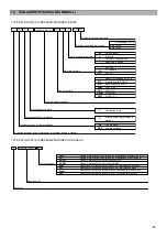
Страница 21: ...20 COLLEGAMENTO A QUADRO DI PROTEZIONE INVERTER A BORDO MOTORE VASCO E SPD H PRESSOSTATO DI AVVIAMENTO POMPA...
Страница 43: ...19 ENGLISH PROTECTION PANEL CONNECTION WITH ON BOARD PUMP INVERTER VASCO E SPD H PUMP STARTING PRESSURE SWITCH...
Страница 48: ...24 ENGLISH 18 UKCA DECLARATION OF CONFORMITY...


