background image

85030 

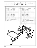
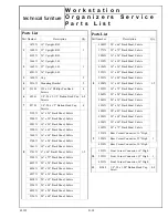
Parts List 


Description 

Qty. 


6074X 

Organizer Frame, 16” x 24” 


6075X 

Organizer Frame, 32” x 24” 


6076X 

Organizer Frame, 36” x 24” 


6077X 

Organizer Frame, 48” x 24” 


6078X 

Organizer Frame, 16” x 30” 


6079X 

Organizer Frame, 32” x 30” 


6080X 

Organizer Frame, 36” x 30” 


6081X 

Organizer Frame, 48” x 30” 


6082X 

Organizer Frame, 16” x 36” 


6083X 

Organizer Frame, 32” x 36” 


6084X 

Organizer Frame, 36” x 36” 


6085X 

Organizer Frame, 48” x 36” 


6086X 

Organizer Frame, 16” x 42” 


6087X 

Organizer Frame, 32” x 42” 


6088X 

Organizer Frame, 36” x 42” 


6089X 

Organizer Frame, 48” x 42” 


5441X 

Organizer Frame, 16” x 48” 


5442X 

Organizer Frame, 32” x 48” 


5443X 

Organizer Frame, 36” x 48” 


6090X 

Organizer Frame, 48” x 48” 


5444X 

Organizer Frame, 16” x 60” 


5445X 

Organizer Frame, 32” x 60” 


5446X 

Organizer Frame, 36” x 60” 


6091X 

Organizer Frame, 48” x 60” 


5450X 

Organizer Frame, 16” x 72” 


5451X 

Organizer Frame, 32” x 72” 


5452X 

Organizer Frame, 36” x 72” 


6109X 

Organizer Frame, 48” x 72” 


Part Number  

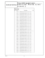
Parts List 


Description 

Qty. 


5447X 

Organizer Frame, 16” x 72” 


5448X 

Organizer Frame, 32” x 72” 


5449X 

Organizer Frame, 36” x 72” 


6092X 

Organizer Frame, 48” x 72” 


6094X 

Cover, 24” 


6095X 

Cover, 30” 


6096X 

Cover, 36” 


6097X 

Cover, 42” 


5437X 

Cover, 48” 


5438X 

Cover, 60” 


5439X 

Cover, 72” 


6375X 

Cover, 24” 


6376X 

Cover, 30” 


6377X 

Cover, 36” 


6378X 

Cover, 42” 


6379X 

Cover, 48” 


6380X 

Cover, 60” 


6381X 

Cover, 72” 


5431X 

Cap 


5434X 

Cover - End Standard, 16” 


5435X 

Cover - End Standard, 32” 


5436X 

Cover - End Standard, 36” 


6093X 

Cover - End Standard, 48” 


84742 

#10AB x 2.25” Phillips Flat Head Screw  varies 

Part Number  

T e c h O r g a n i z e r  
S e r v i c e   P a r t s   L i s t  


technical furniture 

E-2 

Содержание LINX

Страница 1: ...Modular Furniture LINX Modular Furniture Installation manual...

Страница 2: ...lity or otherwise for any special indirect incidental or consequential damage or loss whatsoever including but not limited to damage or loss of use of equipment plant or power system cost of capital l...

Страница 3: ...9 Semi Recessed Monitor A35 Adjustable CPU Holder Nova A38 LINX Worksurface Service Parts List A39 HEIGHT ADJUSTABLE WORKSURFACE ASSEMBLY B Universally Adjustable B1 Single Surface Adjustable B2 Heigh...

Страница 4: ...Panel using the 1 4 20 x 3 4 Phillips pan head machine screws provided Tighten securely See Figure 2 and Figure 2a NOTE Depending on the height of the Modesty Panel being installed it may be necessary...

Страница 5: ...the Worksurface and align its pre drilled holes with those in the Panel and Legs Attach with the 10 screws pro vided See Figure 3a and Figure 3b 3 Turn the unit over and adjust the Glide Feet if neces...

Страница 6: ...rksurface Align the holes in the mounting plate with the appropriate holes in the worksurface and secure using the five 10AB x 1 00 Pan head self tapping screws provided See Tools Required 5 32 Hex ke...

Страница 7: ...nd one 30 side attach the 22 foot to to the leg assembly to be installed on the end of the work surface measuring 24 left or right 2 Place the Worksurface on top of the top supports From underneath al...

Страница 8: ...her two or three screws at each end 2 Place the Worksurface on top of the top supports From underneath align the holes in the top supports and the oval holes in the modesty panels with the pre drilled...

Страница 9: ...ween the two leg assemblies as shown in Figure 2 Align the holes in the in the Modesty Panel with pre drilled holes in the work surface and the holes in the leg assemblies Fasten the Modesty Panel to...

Страница 10: ...ext position the Modesty Panel between the two leg assemblies as shown in Figure 2 Align the holes in the in the Modesty Panel with pre drilled holes in the work surface and the holes in the leg assem...

Страница 11: ...the Tie Plate in place with four 10 x 3 4 screws See Figure 2 Figure 1 NOTE When joining two Linx Workstations as shown in Figure 2 it is recommended that the addi tional Top Support and Tie Plate pr...

Страница 12: ...3 4 Phillips head screw Do not fully tighten the screws at this time See Figure 1 NOTE If two different height Workstations are to be connected assemble the Top Supports so that they are at the same l...

Страница 13: ...ty Panels Next remove the back ing from the Tape Strips and carefully lower the Top back into position See Figure 5 84570 Figure 5 Top Modesty panel 1 4 20 x 3 4 Phillips head screws 10 x 3 4 Phillips...

Страница 14: ...face Align the Corner Support with the pre drilled holes in the Top and fasten with the 10 x 3 4 Phillips head screws See Figure 3 Figure 3 Figure 1 Hole plugs 4 20 x 3 4 Phillips head screws Top supp...

Страница 15: ...t the Top to reposition it as it will tear the Double Faced Tape apart rendering it unusable 4 Place the Top Corner Support over the Top Supports Make sure that the Worksurfaces and edges are flush an...

Страница 16: ...69735 technical furniture Square Rectangular Connector With Corner Support S q u a r e R e c t a n g u l a r C o n n e c t o r w i t h C o r n e r S u p p o r t...

Страница 17: ...20 x 1 2 button head cap screw into the lower rear section of each leg Leave this screw extend ing approximately 1 8 from the face of the leg See Figure 1 inset NOTE If a full height Modesty Panel is...

Страница 18: ...econd person holding the workstations and Connector in place tighten all of the screws See Figure 3 7 Attach the Tie Bar to the front of the workstations Using the Tie Bar as a template drill two 1 8...

Страница 19: ...t this time 5 Install a Tie Plate on each side of the Connector using the 10AB x 3 4 Phillips head screws See Figure 3 6 Adjust alignment of the surfaces and tighten all screws Tools Required Phillips...

Страница 20: ...84253 Corner Connector C u r v e d C o r n e r C o n n e c t o r N o M o d e s t y P a n e l s technical furniture...

Страница 21: ...self tapping screws provided See Figure 2 4 Place the Conference end onto the Bracket Align the predrilled holes in the underside and fasten in place using the 10AB x 3 4 Phillips head screws See Figu...

Страница 22: ...ew Do not fully tighten the screws at this time See Figure 2 NOTE If two different height Workstations are to be connected assemble the Top Supports so that they are at the same level as the lower Wor...

Страница 23: ...head self tapping screws provided See Figure 5 6 With two people turn the Peninsula Worksurface upright and place it onto the Leg Modesty panel assembly and fasten it in place with ten 10 x 3 4 Philli...

Страница 24: ...84913 Bolt on Peninsula P e n i n s u l a B o l t o n technical furniture...

Страница 25: ...the Top Support and the leg Attach it with two 1 4 20 x 3 4 Phillips head screws Tighten all screws securely See Figure 2 NOTE If the 26 Modesty Panel is being installed use three 1 4 20 x 3 4 Philli...

Страница 26: ...ded See Figure 5 8 With two people turn the Peninsula upright and place it onto the Leg Modesty Panel assembly Align the pre drilled holes in the worksurface with the oval holes in the Modesty Panel a...

Страница 27: ...o people turn the Peninsula upright and place it in position against the Worksurface it will be attach ed to See Figure 2 4 Next select two holes in the Connection Bracket one on each side near the ce...

Страница 28: ...A 22 1 Using the 1 4 20 x 2 00 button head cap screws and lock washers provided assemble the base The Leg Connector has tapped holes Insert the screws thru the holes in the C Legs and tighten into the...

Страница 29: ...gning the holes in the Base with the holes in the Top 4 Fasten the Base Assembly to the Top using the eight 10 x 3 4 Phillips head screws and the eight plain washers provided See Figure 2 Next install...

Страница 30: ...ence Table Top 42 1 2178X Round Conference Table Top 48 2 2255X C Leg 4 3 59103 10AB x 75 Phillips Pan Head Thread Forming Screw 8 4 54225 10 Plain Washer 8 5 1242X End Cap 4 6 21333 Glide Foot 4 7 85...

Страница 31: ...s top support Mark the holes and drill no more than 3 4 deep 1A For LMS 72 Surfaces align the fronts as above but align the side with the end of the stiffener Mark the hole locations and drill 5 32 ho...

Страница 32: ...at the rear of the side flanges over the loosened rear screws Next install a 1 4 20 x 3 8 Button head cap screw in the front oval hole of each side flange See Figure 2 Tighten all screws CAUTION The...

Страница 33: ...inder Shelf by engaging the forward screws on the legs into the vertical slots in the Shelf With the Shelf resting on the bottom of the Modesty Panel push the Shelf toward the Modesty Panel allowing t...

Страница 34: ...ls incorporate a stepped design to provide a raceway for running cables horizontally and to exit at the rear to the Wire Covers attached to the supporting legs Cable Retainers are factory installed an...

Страница 35: ...port at the bot tom See Figure 3 NOTE Wire Covers for add on Corner Workstations are common No right or left hand To route cables thru the Wire Cover 1 Remove the desired Wire Cover from the back of t...

Страница 36: ...nd assembly Refer to Figure 1 for handing 1 Attach the Cross Braces to the Side Assemblies using eight 14AB x 3 4 screws See Figure 1 2 Attach the Legs optional to the Side Assemblies using four 14AB...

Страница 37: ...nd must be to the front of the Worksurface See Figure 4 Install a Rubber Stop in the center hole at the rear of each Track with the 6AB x 5 8 screws provided 5 Install the Keyboard Drawer by sliding t...

Страница 38: ...gure 7 NOTE The mousing surface can be attached to either the right hand or the left hand side of the drawer 6 Attach the Palm Rest to the front of the keyboard drawer using the pre drilled holes and...

Страница 39: ...bottom NOTE Do not install the security screws at this time 2 With the assistance of another person lower the monitor through the viewport opening while allowing wires to feed through the back of the...

Страница 40: ...Legs and Worksurface 18 8 5001818 12 Tracking Block 4 9 5001818 13 6AB x 5 8 Screws Tracks security 24 10 5001818 14 Visor 1 11 5001818 15 Leg 2 12 22784 Track 2 13 22289 Rubber Stop 4 14 24968 Palm...

Страница 41: ...R e t r o f i t K i t N o v a c o n t 86270 technical furniture A 34...

Страница 42: ...g Screw 87599 3 8 10 x 1 8 Spacer 1 Insert the Frame into the pre cut opening in the work surface and fasten it in place using the 10AB x 3 8 phillips head thread forming screws See figure 1 NOTE Linx...

Страница 43: ...lon spacers and the four 10 24 x 3 8 phillips pan head thread forming screws provided See figure 3 Install the 10 24 x 3 8 screws with spacers into the pre punched holes just above the front and back...

Страница 44: ...n i t o r c o n t 87522 Parts List Part Number Description Qty 1 8867X Frame Standard Monitor 1 8868X Frame Large Monitor 2 8869X Shelf Standard Monitor 1 8870X Shelf Large Monitor 3 8572X Monitor Sto...

Страница 45: ...n sequence Tools Required None 1 Install the CPU Holder as shown in Figures 1 and 2 2 The CPU Holder can be adjusted as shown in Figure 3 NOVA04 Adjustable CPU Holder technical furniture A 38 Figure 3...

Страница 46: ...7 90 4 4824X Foot Full Depth Leg 21 90 1 2 6717X Foot Full Depth Leg 33 90 5 1242X End Caps pair 2 6 21333 Glide Foot 4 7 68809 5 16 18 x 1 00 Socket Head screw 4 8 8 18950 31 Lock Washer 4 8 9 59103...

Страница 47: ...30 5118X 26 Modesty Panel 36 5119X 26 Modesty Panel 42 5120X 26 Modesty Panel 48 5121X 26 Modesty Panel 54 5122X 26 Modesty Panel 60 5367X 26 Modesty Panel 24 5368X 26 Modesty Panel 30 6134X 26 Modest...

Страница 48: ...Shelf 66 5974X Binder Shelf 72 Part Number L I N X W o r k s u r f a c e S e r v i c e P a r t s L i s t c o n t technical furniture A 41 Parts List Part Number Description Qty 18 10774X Cable Bushing...

Страница 49: ...u r f a c e S e r v i c e P a r t s L i s t c o n t technical furniture A 42 Parts List Description Qty 34 6900X Keyboard Bridge Support 2 35 C855MM Posting Shelf 1 5162X Wire Cover 27 Leg L H 5166X...

Страница 50: ...84567 Linx Worksurfaces Conference Worksurfaces L I N X W o r k s u r f a c e s C o n f e r e n c e W o r k s u r f a c e s technical furniture A 43...

Страница 51: ...84571 Triangular Connector T r i a n g u l a r C o n n e c t o r technical furniture A 44...

Страница 52: ...5 Square Rectangular Connector With Corner Support technical furniture S q u a r e R e c t a n g u l a r C o n n e c t o r w i t h M o d e s t y P a n e l s Square Rectangular Connector With Modesty P...

Страница 53: ...84252 85217 Conference End C o n f e r e n c e E n d technical furniture A 46...

Страница 54: ...84569 84913 L i n k e d P e n i n s u l a B o l t O n P e n i n s u l a technical furniture A 47 Linked Peninsula Bolt on Peninsula...

Страница 55: ...80752 84253 Top Connection Peninsula Curved Corner Connector T o p C o n n e c t i o n P e n i n s u l a C u r v e d C o r n e r C o n n e c t o r technical furniture A 48...

Страница 56: ...81071 B C o n f e r e n c e T a b l e technical furniture A 49...

Страница 57: ...84085 Posting Shelf P o s t i n g S h e l f technical furniture A 50...

Страница 58: ...81046 Storage Shelf S t o r a g e S h e l f technical furniture A 51...

Страница 59: ...84566 Cable Management Components W o r k s t a t i o n C a b l e M a n a g e m e n t c o n t technical furniture A 52...

Страница 60: ...25 30mm screws provided Repeat this procedure for the Front Surface See Figure 2 NOTE The radiused side of both Surfaces face to wards the front of the unit 4 The Front Crank Assembly may be installed...

Страница 61: ...on a 30 wide unit the overall width of the Workstation is 60 1 Attach the Side Extension Support to the Adjustable Base Frame using the two M 8 x 16mm Flat socket head cap screws Tighten securely with...

Страница 62: ...1 2 2519X Support Side Extension 1 3 59103 10AB x 75 Phillips Pan Head Thread Forming Screw 4 4 81718 M8 x 12mm Flat Head Socket Cap Screw 2 Part Number W o r k s u r f a c e S i d e E x t e n s i o n...

Страница 63: ...th the longer portion to the front of the unit 2 Install the left and right hand Top Supports using the four M 8 x 2 25 Socket head screws and 1 00 Spacers Tighten securely with the 6mm Allen wrench I...

Страница 64: ...and onto the drive pin in the Base Frame Fasten the Crank Assembly to the drive pin using the Connector Clip See Figure 3b 4 Place the Worksurface on the Top Supports Align the holes in the Supports...

Страница 65: ...1721 M 8 x 1 00 25mm Socket Head Cap Screw 4 10 18950 Lock Washer 4 11 82737 M 8 x 2 1 Socket Head Cap Screw 4 12 82738 Spacer 4 13 82742 Round Hole Plug 4 14 59844 8 x 2 25 Screw 8 15 1937X 1938X 60...

Страница 66: ...82743 Height Ajustable Worksurface Universally Adjustable VDT Stand H e i g h t A d j u s t a b l e W o r k s u r f a c e s technical furniture B 7...

Страница 67: ...the bottom by inserting the Caster stems into the holes Push the Casters in until they are fully seated See Figure 1 IMPORTANT Install the Locking Casters at the front as shown Mobile Pedestal C843 C...

Страница 68: ...IGHTEN See Figure 1 If a second Back Panel is to be installed slide it down from the top and install the screws DO NOT TIGHTEN See Figure 2 3 Make sure that the bottom of the Back Panel and Up rights...

Страница 69: ...5 4 Install the two Top Caps See Figure 5 IMPORTANT The Linx Organizer must be fastened to the worksurface FASTENING THE ORGANIZER TO A LINX WORKSURFACE Figure 4 10 x 3 4 Phillips pan head screws Mou...

Страница 70: ...he worksurface sides are square to the top and its width is exactly 48 60 ect the template may be usable Mark the holes measure and compare to the chart below before drilling Organizer Size 24 30 36 4...

Страница 71: ...rs TASK LIGHT 24 or 48 Task Light END PANEL INSTALLATION LOCKING COMPARTMENT 1 Two identical End Panels are provided for each Locking Compartment Each End Panel may be used in either the Left hand or...

Страница 72: ...limit of 200 lbs SHELF INSTALLATION 1 There are three factory screws installed along the bottom edge of each End Panel These screws must be backed out approximately 1 8 as shown in Figure 2 inset Afte...

Страница 73: ...re CENTER PANEL INSTALLATION 66 and 72 Locking Compartment The Locking Compartments for the 66 and 72 Organizers require a Center Panel to support the two Top Panel and Receding Door assemblies 1 Loca...

Страница 74: ...rtment See Figure 6 Posi tion the two Door Track hinges against the front flange of the Top Panel The Door edges must be aligned with the outer surfaces of the End Panels Align the slots in the Door T...

Страница 75: ...r the front edge of the Task Light fixture See Figure 8 Remove bulb by rotating it in either direction and then pull ing it away from the mounting sockets 3 Position the Task Light fixture against the...

Страница 76: ...illips head sheet metal screws partially into the holes leaving them pro truding approximately 1 16 See Figure 10 Install the 48 Task Light following the balance of the instructions for the 24 Task Li...

Страница 77: ...or Assembly 24 8192X Receeding Door Assembly 30 8193X Receeding Door Assembly 36 5 8194X Receeding Door Assembly 42 1 2 8195X Receeding Door Assembly 48 8196X Receeding Door Assembly 54 8197X Receedin...

Страница 78: ...80954LX L o c k i n g C o m p a r t m e n t s c o n t technical furniture D 11...

Страница 79: ...ir heads touch the Uprights snug fit DO NOT TIGHTEN See Figure 1 3 Slide the Back Panel down from the top and install the button head cap screws in the same fashion as in step 2 See Figure 1 4 Make su...

Страница 80: ...e 4 IMPORTANT The Linx Organizer must be fastened to the worksurface FASTENING THE ORGANIZER TO A LINX WORKSURFACE Figure 3 10 x 3 4 Phillips pan head screws Mounting brackets 69299 technical furnitur...

Страница 81: ...orations and place the template on the corner of the worksurface as shown in Figure 2 Fold the tab on the opposite end of the template for the other corner of the worksurface Tools Required Phillips h...

Страница 82: ...stall an Upright at each corner of the worksurface by fitting the Uprights down over the Mounting Brackets Secure the Uprights to the Mounting Brackets with the four 1 4 20 x 1 2 Button head cap screw...

Страница 83: ...ck Panel toward the Upright This will allow the threaded weld stud on the Front Connector to clear the Panel Reposition the Panel after the Corner Connectors are installed Install the 1 4 20 x 1 00 Bu...

Страница 84: ...ls Required 5 32 Allen wrench provided Phillips head screw driver Electric drill 1 8 Dia drill bit Required for the installation of the WD06 XX 42 1067mm x 42 1067mm Shelf only CORNER LAMINATE SHELF I...

Страница 85: ...d See Figure 2 Save the Button head cap screws They will be re used in Step 2 2 Fasten one Shelf Side Bracket to each Upright at the desired Shelf height using the Button head cap screws removed in St...

Страница 86: ...XX position it as desired on the Brackets Supports and mark the location of the two holes in the Side Brackets on the bottom of the Shelf With two people remove the Shelf and drill four 1 8 diameter h...

Страница 87: ...pport A 2 3 2289X Rear Shelf Support B 2 4 59103 10AB x 3 4 Phillips Head Thread Forming Screw 4 2371X 12 Shelf 30 Corner Workstation Organizer 5 2372X 12 Shelf 42 Corner Workstation Organizer 1 2373X...

Страница 88: ...p inner surface of each upright using the 1 4 20 x 50 Button head cap screws removed in Step 1 See Figure 2 3 Position the Reception Surface in place on top of the organizer Align the pre drilled hole...

Страница 89: ...42 5415X Reception Counter 15 x 48 5416X Reception Counter 15 x 54 3 5417X Reception Counter 15 x 60 1 5418X Reception Counter 15 x 66 5419X Reception Counter 15 x 72 5671X Reception Counter 15 x 36 E...

Страница 90: ...ecuring them with the 1 4 20 x 3 50 Lag screws and washers provided DO NOT tighten at this time IMPORTANT Be sure to install the Shelf Supports with the mounting clips facing up See Figure 2 See note...

Страница 91: ...ws provided See Figure 5 7 With two people align the shoulder screws in the bottom of the Shelf with the slots in the mounting clips See Figure 5 Insert the shoulder screws into the slots in the moun...

Страница 92: ...t Assembly L H 1 4 2974X Shelf Support Assembly R H 1 5 82246 Spacer 2 Part Number Parts List Description Qty 2960X 24 Rear Panel 2961X 30 Rear Panel 6 2962X 36 Rear Panel 1 2963X 48 Rear Panel 2964X...

Страница 93: ...LINX Organizer Position the panel on the back of the organizer and adjust it vertically or horizontally as necessary See Figure 1 32 or 36 Organizers require two panels Locate and fasten the top panel...

Страница 94: ...ric Panel W606 XX 16 H x 60 W Rear Fabric Panel W678 XX 16 H x 66 W Rear Fabric Panel 1 W726 XX 16 H x 72 W Rear Fabric Panel 1 W530 XX 20 H x 24 W Rear Fabric Panel W531 XX 20 H x 30 W Rear Fabric Pa...

Страница 95: ...9X 20 x 54 Back Panel Fabric 3126X 20 x 60 Back Panel Fabric Part Number Parts List Description Qty 4900X 20 x 66 Back Panel Fabric 3773X 20 x 72 Back Panel Fabric 5050X 16 x 24 Back Panel Fabric 2238...

Страница 96: ...84848 Tack Panel 16 High Back Panels 12 84849 Tack Panel 16 High Back Panels 1 4 84850 Tack Panel 16 High Back Panels 84324 Tack Panel 20 High Back Panels 84325 Tack Panel 20 High Back Panels 84326 T...

Страница 97: ...69299 16 High Corner Organizer W o r k s t a t i o n O r g a n i z e r s S e r v i c e P a r t s L i s t c o n t technical furniture D 30 36 High Organizer...

Страница 98: ...69299 W o r k s t a t i o n O r g a n i z e r s S e r v i c e P a r t s L i s t c o n t technical furniture D 31 16 High Organizer 32 High Organizer...

Страница 99: ...69299 36 High Corner Organizer 32 High Corner Organizer W o r k s t a t i o n O r g a n i z e r s S e r v i c e P a r t s L i s t c o n t technical furniture D 32...

Страница 100: ...69299 36 High Pass Through Organizer W o r k s t a t i o n O r g a n i z e r s S e r v i c e P a r t s L i s t c o n t technical furniture D 33...

Страница 101: ...e desired location on the back of the Worksurface On a Linx Worksur face locate the back of the frame 20 from the back edge of the Worksurface See Figure 1 2 Using the holes in the frame bottom crossb...

Страница 102: ...0 5445X Organizer Frame 32 x 60 5446X Organizer Frame 36 x 60 6091X Organizer Frame 48 x 60 5450X Organizer Frame 16 x 72 5451X Organizer Frame 32 x 72 5452X Organizer Frame 36 x 72 6109X Organizer Fr...

Страница 103: ...ganizer Frame 16 x 42 R H 6 6277X CWS Organizer Frame 32 x 42 R H 1 6279X CWS Organizer Frame 36 x 42 R H 6281X CWS Organizer Frame 48 x 42 R H 6383X CWS Organizer Frame 16 x 48 R H 6285X CWS Organize...

Страница 104: ...ganizer Frame 16 x 42 L H 7 6276X CWS Organizer Frame 32 x 42 L H 1 6278X CWS Organizer Frame 36 x 42 L H 6280X CWS Organizer Frame 48 x 42 L H 6382X CWS Organizer Frame 16 x 48 L H 6284X CWS Organize...

Страница 105: ...0X Corner Post 32 1 6231X Corner Post 36 6232X Corner Post 48 9 6233X Cap 1 10 83508 1 4 20 x 1 5 8 Button Head Cap Screw Part Number TechOrganizer Corner TechOrganizer T e c h O r g a n i z e r S e r...

Страница 106: ...capacity is 300 lbs Linx worksurfaces 400 lbs Workbenches Do not install shelves that are greater than 18 deep Do not install shelves more than 35 above the Work surface 1 Assemble Left hand and Righ...

Страница 107: ...113 dia holes 50 deep in the Worksurface See Figure 2 NOTE If the feet are not 90 to the frame tap the ends with a plastic mallet to correct 4 Attach the frame bottom crossbar to the worksurface using...

Страница 108: ...the board The TechOrganizer frame must be properly attached to the Worksurface prior to panel installation 1 Attach the steel Mounting Channels to the sides of the Organizer frame slotted standards by...

Страница 109: ...a flat blade screwdriver as a lever or a plastic mallet as required 3 Lock the Board in place by installing two 10 24 x 3 4 Phillips pan head thread forming screws into the bottom of the panel See Fi...

Страница 110: ...ard 27 64 High x 32 92 Wide 84908 White Board 31 64 High x 20 92 Wide 84909 White Board 31 64 High x 26 92 Wide 84910 White Board 31 64 High x 32 92 Wide 84925 White Board 43 64 High x 20 92 Wide 8492...

Страница 111: ...64 High x 32 92 Wide 3 6204X Bin Board 27 64 High x 20 92 Wide 1 6205X Bin Board 27 64 High x 26 92 Wide 6206X Bin Board 27 64 High x 32 92 Wide 6207X Bin Board 31 64 High x 20 92 Wide 6208X Bin Board...

Страница 112: ...85089 W h i t e P e g A n d B i n B o a r d s c o n t technical furniture E 12...

Страница 113: ...ase liner from the double faced tape on the back of the Marker Tray 2 Carefully align the bottom of the Tray with the bend line at the bottom of the White Board and center it side to side Now press th...

Страница 114: ...M a r k e r T r a y c o n t Parts List Description Qty 6596X Marker Tray 24 1 6597X Marker Tray 30 1 6598X Marker Tray 36 Part Number 85130 technical furniture E 14...

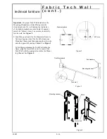
Страница 115: ...st be properly attached to the Worksurface prior to panel installation 1 Attach the steel Mounting Channels to the sides of the Organizer frame slotted standards by align ing the holes in the Channels...

Страница 116: ...nto the TechOrganizer frame by first inserting one side of the Tech Wall onto one Mounting Channel and then snapping the other side onto the opposite Mounting Channel See Figure 3 To facilitate positi...

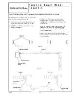
Страница 117: ...e the Mounting Channel align the holes in the channel with the holes in the frame standard and fasten the channel in place using the 8 32 x 3 8 screws See Figure 3b 4 Install the second set of Tech Wa...

Страница 118: ...el 6345X 44 52 x 24 17 Fabric Panel 6346X 12 52 x 30 17 Fabric Panel 6347X 28 52 x 30 17 Fabric Panel 6348X 32 52 x 30 17 Fabric Panel 6349X 44 52 x 30 17 Fabric Panel Part Number F a b r i c T e c h...

Страница 119: ...85082 F a b r i c T e c h W a l l c o n t technical furniture E 19...

Страница 120: ...hown 2 Install the Rear Supports Be sure to locate them at the same height as the Shelf Supports See Figure 1 3 With two people lift and place the shelf onto the Shelf Supports 4 Fasten the shelf to t...

Страница 121: ...Corner Shelf 36 x 72 12 Deep R H 7449X Corner Shelf 24 x 24 18 Deep 7450X Corner Shelf 30 x 30 18 Deep 7451X Corner Shelf 36 x 36 18 Deep 7452X Corner Shelf 42 x 42 18 Deep 7453X Corner Shelf 48 x 48...

Страница 122: ...85093 C o r n e r L a m i n a t e H o o k O n S h e l v e s c o n t technical furniture E 22...

Страница 123: ...Boulevard Cleveland OH 44122 United States Eaton com 2018 Eaton All Rights Reserved Printed in USA Publication No IB211002EN May 2018 Follow us on social media to get the latest product and support i...

Отзывы: