Service Manual for Flexible Batch Broiler, CE Version
21
6/19/2014
SM-BR-BR-0007
NOTE:
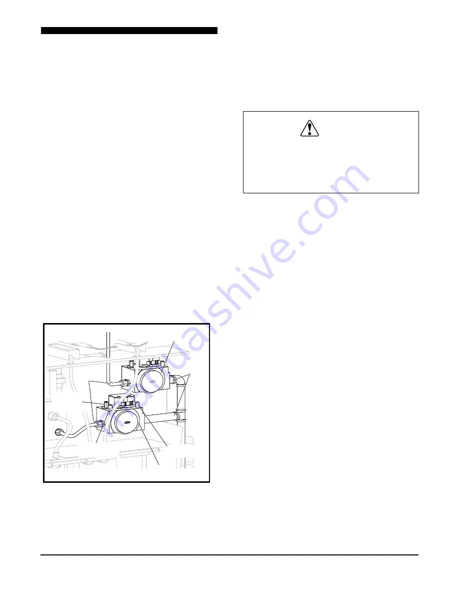
Combo Gas Valves are not serviceable
and must not be disassembled.
1. Shut off gas to broiler.
2. Remove the Upper Lift Off Panel and Lower
Control Side Service Panel. Refer to the
COVERS and PANELS section of the manual.
3. Disconnect gas line going to the burner
assembly at the Combo Gas Valve.
4. Tag and disconnect wires to the Combo Gas
Valve.
5. Using a pipe wrench unscrew the Combo Gas
Valve from the input gas line.
6. Reverse procedure to install a Combo Gas
Valve. Make sure the new Combo Gas Valve
is installed in the right direction.
NOTE:
Use Anti-Seize Technologies TFE1400
on all pipe threads when replacing a Combo Gas
Valve.
7. Check all gas connections for leaks.
8. Ensure proper gas valve pressure.
Burner
Gas Lines
Input
Gas Lines
Upper
Combo Gas Valve
Lower
Combo Gas Valve
Incoming
Pressure Tap
Outgoing
Pressure Tap
Outgoing
Pressure
Adjustment
Combo Gas Valves
Cook Chamber Temperature Probe
The Cook Chamber Temperature Probe connects
to the bottom of the Control Board and is located
on the back of the broiler.
WARNING
DIsCONNECT THE ELECTRICAL
POWER TO THE BROILER AND
FOLLOW LOCKOUT / TAGOUT
PROCEDUREs.
1. Remove the Lower Control Side Service Panel.
Refer to the COVERS and PANELS section
of the manual.
2. Remove the Rear Panel. Refer to the COVERS
and PANELS section of the manual.
3. Disconnect the Cook Chamber Temperature
Probe connector at the bottom of the Control
Board.
4. Remove the Cook Chamber Temperature
Probe from the bracket by pushing down gently
on the bracket.
5. Pinch the two grommets in the electrical
compartment to remove them.
6. Slide the Cook Chamber Temperature Probe
out of the broiler.
7. Reverse procedure to install a Cook Chamber
Temperature Probe, ensuring the two
grommets are reinstalled.
8. Ensure the Cook Chamber Temperature Probe
is seated correctly on the its mounting bracket.
The notch on the sheath must be locked on
the bracket.


