ENiQ® Wall Readers & Terminals
_____________________________________________________________________________________
14
Please note! The installation direction of the ENiQ AccessManager® and
the ENiQ
®
Passive Reader is marked with an arrow (Top). The arrow
must point upwards. In an installed condition, the DIP switches are at the
lower left.
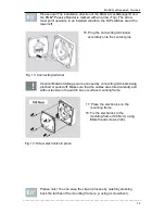
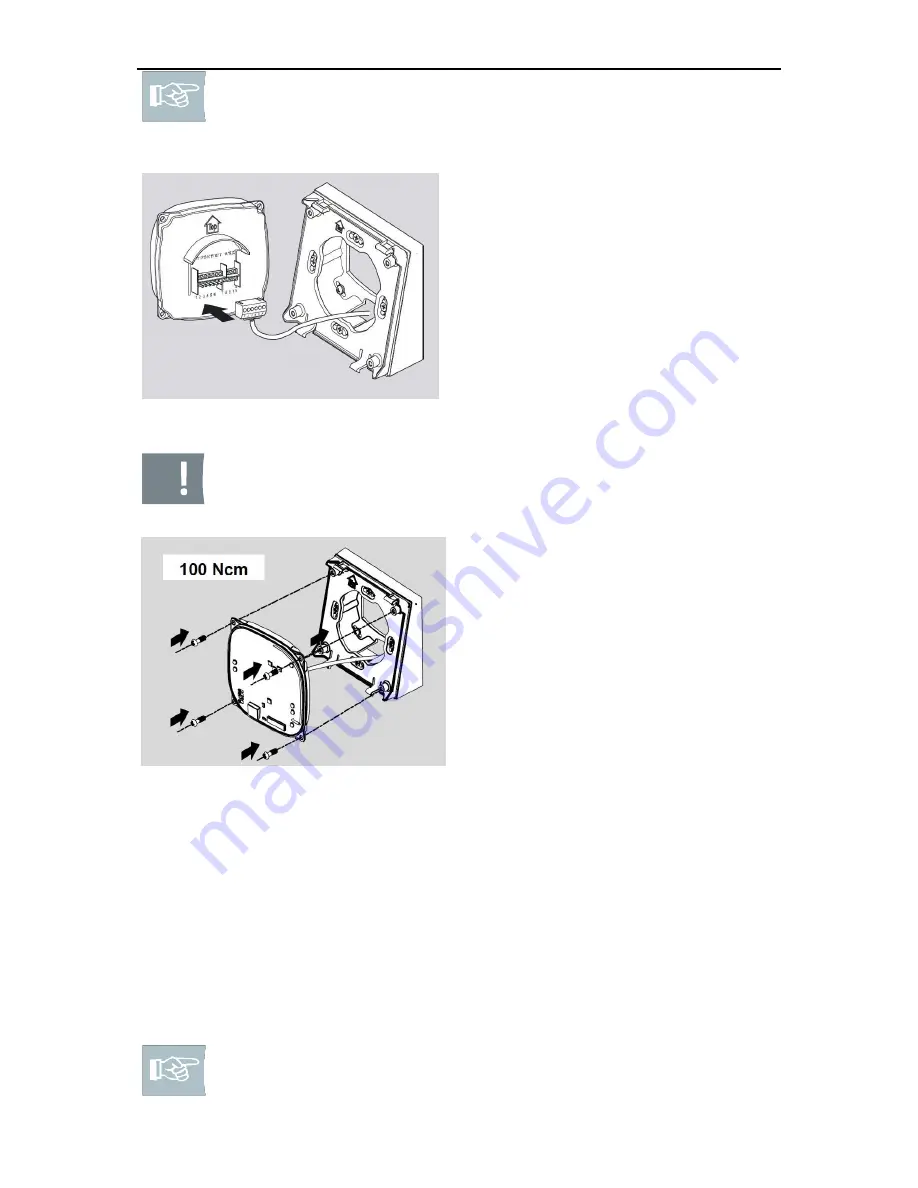
16. Plug the connecting terminal(s)
accurately onto the contact pins.
Fig. 13: Connecting terminal
Caution! Material damage can be caused by connecting terminals being
pinched or pulled off. Make sure that the cables are stored carefully and
without tension in the switch box or surface mounting frame.
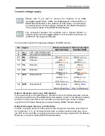
17. Place the electronics on the
mounting frame.
18. Fix the electronics to the
mounting frame (100 Ncm) using
fillister head screws (3x8).
Fig. 14: Screw electronics in place
Please note! You can ease the clip-on process by carefully pressing
back the latches of the mounting frame (e.g. using a screwdriver).

