background image

ENiQ® Wall Readers & Terminals


_____________________________________________________________________________________ 


Proceed according to the sequence described and observe the notes and 
figures. 


Caution! When installing the system, always comply with the 
regulations of the German Association for Electrical, Electronic & 
Information Technologies (VDE) and your local power supply 
company. 


Caution! Material damage can be caused by the excessive 
tightening of screw fittings. Always observe the specified 
tightening torques. 


Caution! If you wish to operate the ENiQ AccessManager® or ENiQ 
AccessManager® Terminal with an ENiQ

®

 Passive Reader via the 

RS485 interface, DIP switches 1 and 2 on the controller and on the 
ENiQ

®

 Passive Reader must be switched ON (see page 13). Where 

more than one ENiQ

®

 Passive Reader is used, note and follow the DIP 

switch settings on pages 14 and 15. 
 
Caution! With an ENiQ

®

 Module Reader DIP switches 1 and 2 of the 

ENiQ AccessManager® or ENiQ AccessManager® Terminal 
controller, connected to an external reader via the RS485 interface, 
must be set to ON. The ENiQ

® 

Module Reader is configured this way 

in the factory.


Please note! As a voltage supply for the ENiQ AccessManager®, 
ENiQ AccessManager® Terminal or ENiQ AccessManager® ITT you 
require a stabilised, sufficiently dimensioned 
12 V to 24 V AC/DC power supply which is not included in the 
scope of delivery. Alternatively, you can set up the voltage supply 
via Power over Ethernet (PoE) (applies for the controller of HiSec 
variants only). 
 
Please  note!  If  you  wish  to  connect  the  controller  of  an  ENiQ 
AccessManager®  HiSec,  ENiQ  AccessManager®  Terminal  HiSec  or 
ENiQ

®

 Module Reader to the network via PoE (Power over Ethernet), 

an external power source is always required for the Passive Reader(s) 
or the external reader of the ENiQ

®

 Module Reader. 


Please note! As a voltage supply for the ENiQ

®

 Module Reader you 

require a stabilised, sufficiently dimensioned 12 V to 24 V DC power 
supply which is not included in the scope of supply. 


The  connection  between  the  controller  and  a  Passive  Reader  or 
external reader by PoE is 

not

 possible. The connection must be set up 

as RS 485. (See page 22 onwards)  

Содержание ENiQ Access Manager ITT

Страница 1: ...Installation and Operating Instructions ENiQ Wall Readers Terminals IT no 298476 0 d 07 16 Version 1 0 ...

Страница 2: ...________________________________________ 2 ENiQ AccessManager ENiQ AccessManager Compact ENiQ AccessManager HiSec ENiQ AccessManager Terminal ENiQ AccessManager Terminal Compact ENiQ AccessManager Terminal HighSec ENiQ Access Manager ITT ENiQ Module Reader ENiQ Passive Reader ...

Страница 3: ...c 22 Configuration ENiQ AccessManager HiSec ENiQ AccessManager Terminal HiSec 25 Connection ENiQ Module Reader 26 Installation of a VOX IO Touch reader 28 Installation of a VOX IO Easy reader 32 Installation of a Siedle RITTO PORTIER reader 35 Installation of a RELINO reader 38 Installation of a Baudisch RITTO ACERO Behnke reader 42 Installation of an ELCOM reader 44 Configuration ENiQ Module Read...

Страница 4: ...an authorised locking medium 62 Tag is authorised at the ENiQ AccessManager Terminal conventional and intelligent 63 Tag is authorised at the ENiQ AccessManager ITT conventional and intelligent 64 Recognition of an unauthorised locking medium 66 Permanently open mode 66 Permanently closed mode 67 Programming and management with software 69 Maintenance 70 Storage care 70 Disposal 70 Dimensional dra...

Страница 5: ...iting intelligent wall reader reading and writing query of authorisation switching of an actuator and extension of the validity of authorisations controller and reader in one device with up to one passive reader Access Manager ITT Compact Intelligent wall reader reading and writing intelligent wall reader reading and writing query of authorisation switching of an actuator extension of the validity...

Страница 6: ...B RF stick Master card Programming card Locking medium Permanent open card day permanent closed card day Surface mounting frame incl screw set each including 4 Spax screws 3 x 25 Phillips fillister head 4 washers and 4 dowels S4 Required components that are not supplied by DOM Standard outlet sockets if not mounted on wall with surface mounting frame Depending on the external reader variant click ...

Страница 7: ...ng media and other components must be kept out of the reach of small children Small parts may be swallowed Caution Material damage due to improper storage If you store the DOM device or other product components for an extended period prior to assembly store all the components in their original packaging in a dry dust free location Caution Damage due to improper installation and operation Read thes...

Страница 8: ...Terminal controller connected to an external reader via the RS485 interface must be set to ON The ENiQ Module Reader is configured this way in the factory Please note As a voltage supply for the ENiQ AccessManager ENiQ AccessManager Terminal or ENiQ AccessManager ITT you require a stabilised sufficiently dimensioned 12 V to 24 V AC DC power supply which is not included in the scope of delivery Alt...

Страница 9: ...ons cannot access the controller Please note Metallic objects in the immediate vicinity of the DOM devices or other sources of interference may reduce the range Please note The reading fields of two readers can mutually influence one another Always install the units at sufficient distances from each other more than 50 cm to counteract mutual interference At smaller distances an authorised locking ...

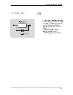
Страница 10: ..._____________________ 10 Fig 1 Flyback diode Please note A flyback diode must be used to trigger actuators which constitute an inductive load coil e g door openers magnetic clamps etc with direct current supply The flyback diode must be used anti parallel to the inductive load see illustration ...

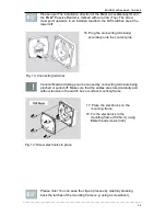
Страница 11: ...unting frame 2 If you use the surface mounting frame drill the holes as drawn and insert the dowels S4 3 Align the surface mounting frame so that the upper edge runs horizontally During this the surface mounting frame can be aligned to all four sides 4 Fix the surface mounting frame in place with the washers and the Spax screws 3x25 Please note The installation direction of the mounting frame is m...

Страница 12: ...g 5 Attach mounting frame Please note Installation of the DOM devices except for the external reader unit ENiQ Module Reader and the cover are identical for switch box and surface mounting frame The following figures therefore only illustrate installation with a surface mounting frame Caution Do not tighten the screws of the connecting terminals as long as the terminals are plugged in You may dama...

Страница 13: ...ive loads such as E openers always heed the max permissible voltage sustaining capacity and current carrying capacity of the DOM device Voltage and current peaks caused by feedback effects can lead to the destruction of the input assemblies If this is not guaranteed please make sure voltage supply is separate Fig 7 Connect the connection cable 11 Loosen the clamping screws if necessary 12 Remove t...

Страница 14: ...nal s accurately onto the contact pins Fig 13 Connecting terminal Caution Material damage can be caused by connecting terminals being pinched or pulled off Make sure that the cables are stored carefully and without tension in the switch box or surface mounting frame 17 Place the electronics on the mounting frame 18 Fix the electronics to the mounting frame 100 Ncm using fillister head screws 3x8 F...

Страница 15: ...re Fig 15 Cover for wall casing If you want to remove the cover again later carefully press the two latches back e g with a screwdriver and pull the cover off the mounting frame Disassembly of the remaining components is carried out in the reverse order of installation The installation instructions of the respective reader variant must be followed for installation of an ENiQ Module Reader ...

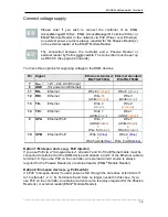
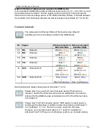
Страница 16: ...utput 14 TD Transmit path output 15 Ö Opener contact output Output changeover contact actuator 16 C Common contact output 17 S Closer contact output 18 RxD Receive RS232 RS485 Connection Reader control unit Reader Reader 19 TxD RS232 RS485 20 GND Ground for RS232 RS485 Please note There are DIP switches and LEDs on each unit The required operating mode is set using the DIP switches Always adjust t...

Страница 17: ...ches Switch Position Function 1 ON RS485 terminating resistor activated OFF RS485 terminating resistor deactivated 2 ON RS485 mode activated RS232 mode deactivated OFF RS485 mode deactivated RS232 mode activated 3 ON Service mode OFF Normal mode 4 ON Status LEDs activated OFF Status LEDs deactivated Caution Ensure a suitable voltage supply and note the positions of the DIP switches ...

Страница 18: ... 6 green 12 RD Ethernet Wire 3 white orange Wire 3 white green 13 TD Ethernet Wire 2 green Wire 2 orange 14 TD Ethernet Wire 1 white green Wire 1 white orange 9 SPA Ethernet PoE Wire 7 white brown Wire 8 brown Wire 7 white brown Wire 8 brown 10 SPB Ethernet PoE Wire 4 blue Wire 5 white blue Wire 4 blue Wire 5 white blue Option 1 Mid span device e g PoE injector If you use PoE via a mid span device...

Страница 19: ... Wire 6 green 12 RD Ethernet Wire 3 white orange Wire 3 white green 13 TD Ethernet Wire 2 green Wire 2 orange 14 TD Ethernet Wire 1 white green Wire 1 white orange 9 SPA Ethernet PoE Wire 7 white brown Wire 8 brown Wire 7 white brown Wire 8 brown 10 SPB Ethernet PoE Wire 4 blue Wire 5 white blue Wire 4 blue Wire 5 white blue Data transmission always takes place at terminals 11 to 14 Please note If...

Страница 20: ...C S are available You can connect potential free switches or buttons to the inputs These inputs must be occupied according to the stored configuration The standard configuration is factory set Input IN1 is the door contact opener and input IN2 the release button closer Please note Note the maximum cable resistance and the maximum cable length specified on the technical data sheet Caution For desig...

Страница 21: ... LED flashes lilac during the reading writing process Once the reading writing process has been completed the lower LED lights up green for as long as contact is maintained Then the lower LED goes off and the upper LED lights up red permanently again The output is triggered for the set contact exposure time refer also to page 23 This is set to 5 seconds in the condition on delivery During this tim...

Страница 22: ... potential free relay changeover contact One potential free opener contact C Ö and one potential free closer contact C S are available You can connect potential free switches or buttons to the inputs These inputs must be occupied according to the stored configuration The standard configuration is factory set Input IN1 is the door contact opener and input IN2 the release button closer Please note N...

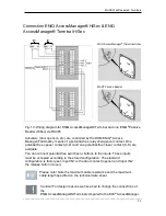
Страница 23: ...h installation check all the connections again If the wiring is not done correctly system components can become damaged Connection ENiQ AccessManager HighSec with two Passive Readers ENiQ AccessManager HiSec ENiQ Passive Reader 1 ENiQ Passive Reader 2 Fig 11 Wiring diagram for ENiQ AccessManager and two ENiQ Passive Readers HiSec via RS485 ...

Страница 24: ...______________________________________________________________________________ 24 Connection ENiQ AccessManager HighSec with three Passive Readers ENiQ AccessManager HiSec ENiQ Passive Reader 1 ENiQ Passive Reader 2 ENiQ Passive Reader 2 ...

Страница 25: ...upper red LED goes off and the lower LED flashes lilac during the reading writing process Once the reading writing process has been completed the lower LED lights up green for as long as contact is maintained Then the lower LED goes off and the upper LED lights up red permanently again The output is triggered for the set contact exposure time refer also to page 23 This is set to 5 seconds in the c...

Страница 26: ...Unlike the ENiQ AccessManager Terminal the external reader of the ENiQ Module Reader cannot be operated via an AC voltage supply The 10 pole connection terminal for the readers of the following ENiQ Module Reader variants Siedle Baudisch Behnmke ELCOM RITTO ACERO RITTO PORTIER These readers are connected to the ENiQ AccessManager Terminal via the following terminals External reader Controller ACM ...

Страница 27: ...cted to the ENiQ AccessManager Terminal via the following terminals External reader Controller ACM ACM T Terminal 8 Ub Terminal 7 12 24 V Terminal 7 Ground Terminal 8 GND Terminal 1 Data A Terminal 18 RxD A Terminal 2 Data B Terminal 19 TxD B Actuators door openers etc are controlled by the DOM ENiQ Access Manager Terminal by means of a potential free relay changeover contact One potential free op...

Страница 28: ... Terminals _____________________________________________________________________________________ 28 Installation of a VOX IO Touch reader Structure of the surface mounted variant Structure of the flush mounting variant ...

Страница 29: ...e screw plug in terminal from the reading module and wire it according to the respective wiring diagram A corresponding connection diagram is included with every reader Caution The reader must be wired up in a de energised state i e the operating voltage may only be switched on after the reader has been completely installed Flush mounted variant Use the screws provided to screw the wall bracket to...

Страница 30: ...red connection terminal on the reading module Set the reading module flat onto to the wall bracket or onto the surface mounted casing pushing the connection cable with the reading module back into the flush mounted box or surface mounting casing Push the reading module downwards until the reading module latches in place on the wall bracket or surface mounted casing Once it is clipped in place push...

Страница 31: ...elease the locking strip To do this insert a screwdriver with a max 4mm blade into the release openings and press until the locking mechanism is released Pull the released locking strip out and remove it from the reading module Push the reading module up release and lift it forwards and off Dimensions Flush mounted variant Surface mounted variant ...

Страница 32: ...____________________________________________________________________ 32 Installation of a VOX IO Easy reader Structure of the surface mounted variant Structure of the flush mounting variant Dimensions Flush mounted variant Surface mounted variant ...

Страница 33: ...g to the respective wiring diagram A corresponding connection diagram is included with every reader CAUTION The reader must be wired up in a de energised state i e the operating voltage may only be switched on after the reader has been completely installed Fit the back plate Flush mounted variant Use the screws provided to screw the back plate to a DIN device box with a device screw spacing of 60m...

Страница 34: ...ing module Fix the reading module to the back plate insert it into the two safety clips at the top Press the reading module towards the back module until the locking mechanisms on the left and right clip in completely When the clip in process is successful you will hear or even feel clear click After the clip in process has been successfully completed screw a safety screw in place if necessary ...

Страница 35: ..._______ 35 Installation of a Siedle RITTO PORTIER reader The installation of a RITTO PORTIER reader is similar to installation of a Siedle reader Please heed the installation instructions from the respective frame manufacturer Structure of the surface mounted variant Structure of the flush mounting variant ...

Страница 36: ...teel Module according to the Siedle Vario installation instructions Centre the combined terminal turned through approx 45 anti clockwise on the bearing plate and lock in place by turning one eighth of a turn clockwise so that the terminal description can be read vertically above one another Use cable holders to press the connection cables onto the casing base Connect the combined terminal strip in...

Страница 37: ...________________________ 37 Apply slight pressure to clamp the reading module for Siedle Vario 611 Siedle Vario Steel against the moving locking bar and lock into place on the opposite side To remove the reading module the vario key is inserted into the release opening using slight pressure ...

Страница 38: ...tion of a RELINO reader Structure Transparent cover detachable Front module reading section with safety screws Standard intermediate frame Cover frame Fixing screws Back module interface Flush mounted DIN device box device screw spacing 60 mm Guide strips Direct connector pin Guide openings Direct connector socket TOP marking ...

Страница 39: ...y be switched on after the reader has been completely installed Installation Following complete electric wiring of the back module use the screws provided to screw it to a standard size 55 flush mounted box and align horizontally Heed the TOP marking arrow must be pointing upwards Rework the standard intermediate frame in the corners if necessary depending on the switch manufacturer or switch rang...

Страница 40: ...e sabotage contact does not become mechanically damaged Position the cover frame with the standard intermediate frame in place on the back module and hold it tight Insert the front module with the guide strips into the guide openings of the back module Care must be taken that all the direct connector pins are inserted into the socket of the back module without twisting Then press the front module ...

Страница 41: ... cover and standard intermediate frame are automatically fixed and held in this position Click the transparent cover with inserted design film and snap fit frame locked in place flat from the front flat onto the front module insert the snap fits into the insertion openings and press in place Care must be taken that the transparent cover with inserted design film and snap fit frame are tightly lock...

Страница 42: ...________________________________________________________________________________ 42 Installation of a Baudisch RITTO ACERO Behnke reader Structure of the reader with front plate information module Structure of the reader in metal panel ...

Страница 43: ...ENiQ Wall Readers Terminals _____________________________________________________________________________________ 43 Dimensions without front plate Dimensions with front plate information module ...

Страница 44: ...eaders Terminals _____________________________________________________________________________________ 44 Installation of an ELCOM reader Installation in the ELCOM Modesta frame system Installation in metal panel ...

Страница 45: ...ENiQ Wall Readers Terminals _____________________________________________________________________________________ 45 Dimensions for installation in metal panel Dimensions for reader without module plate ...

Страница 46: ...LED goes off and the upper LED lights up red permanently again With the external reader of the ENiQ Module Reader all the LEDs flash in their respective colour during the reading writing process Once the reading writing process has been completed the green LED lights up for as long as contact is maintained Then the green LED goes off and the red LED lights up permanently again The output is trigge...

Страница 47: ...ster card Please note The programming method described below using the master and programming card is always carried out at the DOM device Putting into operation initial programming and management of the ENiQ AccessManager Terminal Compact HiSec and ENiQ AccessManager ITT is always done with the aid of the ENiQ Access Management software and is described in detail in the quick guides which you wil...

Страница 48: ...e power failure Check the time and date after a power failure 1 Set up the voltage supply ENiQ AccessManager Compact HiSec ENiQ AccessManager Terminal Compact HiSec and ENiQ AccessManager ITT The lower LED briefly flashes green three times emitting an acoustic signal each time Then the upper LED is lit red permanently Connected ENiQ Passive Readers The upper LED briefly flashes red three times emi...

Страница 49: ...sManager The upper LED lights up red green yellow blue and violet in succession for initialisation on the reader that has just been recognised Then the upper LED flashes red three times emitting an acoustic signal each time This process is repeated once per reader Until all the readers connected have been recognised the two LEDs flash alternately in the signal sequence in red and violet Once all t...

Страница 50: ...ave been installed properly and recognised by the controller ENiQ AccessManager Compact ENiQ AccessManager Terminal Compact and ENiQ AccessManager ITT With the voltage supply connected the upper right hand LED lights up yellow Please note If the upper right hand LED does not light up check the voltage supply connection Status LED voltage When the Ethernet cable is connected the lower right hand LE...

Страница 51: ... ENiQ AccessManager HiSec with two readers The upper LED is lit orange Status LEDs for two readers Please note If the upper LED does not light up check both readers If the upper LED is lit green check reader 1 If the upper LED is lit red check reader 2 ENiQ AccessManager HiSec with three readers The upper LED is lit orange The lower LED is lit green Status LEDs for three readers Please note If non...

Страница 52: ...does not have any contact to the ENiQ AccessManager controller The red LED signals that a transponder is authorised The ENiQ Module Readers of the variants Baudisch Behnke ELCOM RITTO ACERO RITTO PORTIER Siedle have two separate LEDs The left hand LED is a multi colour LED that can light up green and yellow The right hand LED is a red LED If the reader does not have any contact to the ENiQ AccessM...

Страница 53: ...nd emitting an acoustic signal each time Each acoustic signal means one second of contact exposure time 3 Hold the master card in front of the DOM device again in accordance with the required contact exposure time Please note The signalling to any ENiQ Passive Readers connected only shows that the controller is busy setting the contact exposure time After the process has been completed the upper L...

Страница 54: ..._____________________________________________________________________________ 54 Setting contact exposure time Leave in the field Continue to leave in the field As soon as the contact exposure time has been reached remove the master card ...

Страница 55: ...a and programming media programming cards software solutions Transmission of system parameters via ENiQ AccessManagement software to the end devices Programming card The programming card has the following functions Creation or deletion of individual closing media Deletion of all closing media Locking medium key fob Clip Tag card etc Locking and opening Permanently open card tag The permanently ope...

Страница 56: ...ree times and is then lit red permanently after the voltage supply has been connected the data time are not correct or another fault has been recognised by the firmware Opening and locking To open or lock the door you must only hold an authorised locking medium a short distance 1 cm in front of the DOM devices These distances can vary depending on the locking medium Please note If the controller i...

Страница 57: ...amming card flat at a short distance in front of the DOM device controller with HiSec then remove the master card again The lower LED briefly flashes green twice emitting an acoustic signal each time 2 Then present the programming media or locking media that you wish to create When you present a programming medium or locking medium the lower LED flashes green once emitting an acoustic signal each ...

Страница 58: ...all Readers Terminals _____________________________________________________________________________________ 58 Creating programming media 1 2 5 Wait 5 seconds or Creating closing media 1 2 x Wait 5 seconds or ...

Страница 59: ... a programming medium or locking medium the upper LED flashes red once emitting an acoustic signal each time The red LED is then lit permanently again Please note The signalling to any ENiQ Passive Readers or external readers connected only shows that the controller is busy After the process has been completed the upper LED on the ENiQ Passive Readers is lit red again permanently With the ENiQ Mod...

Страница 60: ...ENiQ Wall Readers Terminals _____________________________________________________________________________________ 60 Deleting closing media 1 2 x Wait 5 seconds or ...

Страница 61: ...ramming card again The lower LED briefly flashes green twice emitting an acoustic signal each time 2 Hold the master or programming card flat a short distance in front of the DOM device controller for HiSec again and then remove the master or programming card The upper LED flashes red once briefly and one long emitting an acoustic signal each time Please note The signalling to any ENiQ Passive Rea...

Страница 62: ...ltage supply OK basic state The upper LED is lit red permanently ENiQ AccessManager ENiQ AccessManager Terminal ENiQ AccessManager ITT ENiQ Module Reader ENiQ Passive Reader external reader of the ENiQ Module Reader Recognition of an authorised locking medium To open or lock the door you must only hold an authorised locking medium a short distance 1 cm in front of the DOM device These distances ca...

Страница 63: ...ntact exposure time the green LED goes off and the red LED is lit again permanently ENiQ AccessManager ENiQ Passive Reader external reader of the ENiQ Module Reader Tag is authorised at the ENiQ AccessManager Terminal conventional and intelligent A The conventional or intelligent locking medium is authorised and is not taking part in extension of the authorisation period The changeover contact is ...

Страница 64: ... extension of authorisation period or if programming is cancelled both LEDs flash briefly and the acoustic signal is repeated three times In this case the changeover contact is not actuated and the locking medium is rejected as though it were an unauthorised locking medium The upper LED then flashes red briefly again twice The upper red LED goes off on the other unit connected ENiQ AccessManager T...

Страница 65: ...een for the set contact exposure time and you will hear an acoustic signal DOM ACM ITT Mifare C The intelligent locking medium is authorised is taking part in the data update but data updating has not worked If an error has occurred during programming of the data or if programming is cancelled both LEDs flash briefly and the acoustic signal is repeated three times In this case the changeover conta...

Страница 66: ... ENiQ Module Reader open permanently As long as the mode is active all persons have access no matter whether they have an authorised locking medium available or not Please note To be able to use the permanently open mode create the permanently open card tag according to the description on page 26 Setting permanently open mode Hold the authorised permanently open card tag directly 1 cm in front of ...

Страница 67: ...medium was presented flashes green briefly three times The lower green LED goes off on all other units connected Unit at which the locking medium was presented All other units Permanently closed mode You can use a permanently closed card tag to block the ENiQ AccessManager ENiQ Passive Reader or ENiQ Module Reader permanently As long as the mode is active no one has access even if they have an aut...

Страница 68: ...se note If you have set the permanently closed mode you can use the permanently open card tag at the ENiQ AccessManager ENiQ Passive Reader or ENiQ Module Reader to switch directly to the permanently open mode You do not switch back to the normal state Please note If voltage fails with permanently closed mode enabled the permanently closed mode is retained When the voltage supply is restored the p...

Страница 69: ...ia software These include among others Read out of the event memory Allocation of daily and weekly schedules Deletion of individual closing media that are no longer available Adjusting different parameters such as contact exposure time Creation and deletion of connected ENiQ Passive Readers Querying of the ENiQ Passive Readers or external readers of the ENiQ Module Reader stored in the ENiQ Access...

Страница 70: ...tion or after use store them in their original packaging in a dry dust free location Caution Material damage can be caused by the use of aggressive detergents Do not use aggressive detergents Clean the housing and closing media only using a soft damp leather cloth without detergent Disposal Please note that the DOM devices consist in part of electronic components that require special disposal Duri...

Страница 71: ...y DOM SICHERHEITSTECHNIK GMBH CO KG DE D 50321 Brühl www dom group eu DOM SCHWEIZ AG CH 8852 Altendorf www dom group ch DOM NEDERLAND NL 2491 DH Den Haag www dom group nl DOM SICHERHEITSTECHNIK GMBH A 1140 Wien www dom at HOBERG NV B 1300 Wavre www hoberg be DOM POLSKA SP Z O O PL 42 202 Częstochowa www dom polska pl DOM CR S P A IT 10154 TORINO www dom cr it DOM UK LTD GB Birmingham B69 4LT www r...

Страница 72: ...ENiQ Wall Readers Terminals _____________________________________________________________________________________ 72 Dimensional drawing ...

Отзывы: