ENiQ® Wall Readers & Terminals
____________________________________________________________________________________
13
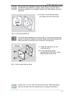
10. Carefully pull out the plug-in
connecting terminals on the back of
the electronics.
Fig. 6: Connecting terminals
Caution! When selecting and connecting external components
(actuators, etc.), comply with the values specified in the technical data
sheet for the voltage sustaining capability and the current carrying
capacity of the inputs/outputs of the respective DOM device. The
manufacturer assumes no liability for damage resulting from the use of
unsuitable external components.
Please note! During joint operation of DOM devices and inductive loads
(such as E-openers) always heed
the max. permissible voltage sustaining capacity and current carrying
capacity of the DOM device. Voltage and current peaks caused by
feedback effects can lead to the destruction of the input assemblies. If
this is not guaranteed, please make sure voltage supply is separate.
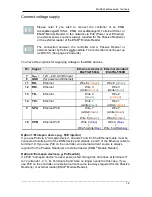
Fig. 7 Connect the connection cable
11. Loosen the clamping screws if
necessary.
12. Remove the insulation from the
cable ends: cable sheathing 40
mm, single wire 5 mm.
13. Attach suitable
wire end ferrules if necessary.
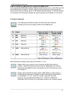
14.
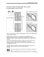
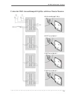
Connect the connection wires
according to the following wiring
diagram (from page 13 onwards).
15. Tighten the clamping screws
(50 Ncm).
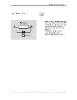
To record events or generate a warning message, a potential-free door contact
switch can be connected, for example. If this contact is actuated, this is
indicated in the event memory of the DOM device.

