ENiQ® Wall Readers & Terminals
_____________________________________________________________________________________
12
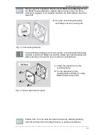
7. Align the mounting frame so that the
upper edge also runs horizontally.
8. Tighten the fixing screws
(100 Ncm).
100 Ncm
Fig. 4: Screw mounting frame in place
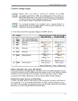
9. If you use a switch box, screw the
mounting frame directly onto the
switch box using the fixing screws
(3x12).
Fig. 5: Attach mounting frame
Please note! Installation of the DOM devices (except for the external
reader unit ENiQ
®
Module Reader) and the cover are identical for
switch box and surface mounting frame. The following figures therefore
only illustrate installation with a surface mounting frame.
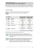
Caution! Do not tighten the screws of the connecting terminals as long
as the terminals are plugged in. You may damage the contact pins.
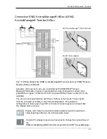
Caution! The radio antenna is exposed and is not cast-in. Do not bend
the radio antenna on the DOM device, as this may impair the quality of
the wireless transmission.

