


24.7.12
Instruction manual LOCON 24, 48, 64, LTC, TERM 24 and TERM 6 V. 8.8
79
Deutschmann Automation GmbH & Co. KG
Operation via TERM 24
14.6.3
Operation mode of the shift register
The parameters of the shift register “data, pulse and reset“ are firmly assigned to the upper mark-
ers.
Here the following assignment applies:
M16 =
Shift register - Reset, if 1
M15 =
Shift register - Data input
M14 =
Shift register - Pulse (leading edge)
14.6.3.1
Example for the use of a shift register
Referring to bottle manufacturing the finished product has to be analyzed for various criterions.
Therefore the bottles are handed over to a rotary table. For the examination they are placed in a
mechanically fixed position, in order to be driven past the different inspection equipment. The ini-
tialization of the test equipment is carried out through the standard outputs of the cam control.
Since it can always happen that no bottle is available when it comes to the supply of the part
under test, for instance due to a tailback on the feed belt or when a batch is coming to an end,
this would result in an error message of the camera. A possibility to avoid this is to use the shift
register integrated in the cam control.would be, to place an approximating pick-up at any test
position and to report the existence of a bottle to the test equipment. In order to realize that pos-
sibility, one single approximating pick-up at the intake to the rotary table is required. The informa-
tion about the existence of a specimen is reported from the approximating pick-up through the
input of the cam switch unit to the shift register. Each Bit of the shift register corresponds to tak-
ing up one bottle in the rotary table. A binary One in the shift register shows the existence of a
bottle, whereas a Zero indicates the lack of a bottle. The Bit, that corresponds to the position of
the inspection equipment, is now linked to the output of the cam switch unit with an AND-connec-
tion, so that the camera belonging to it will only be triggered, in case a bottle for the inspection is
actually available.
14.6.4
Trigger conditions
Symbol
Significance
Leading edge
Trailing edge
14.6.5
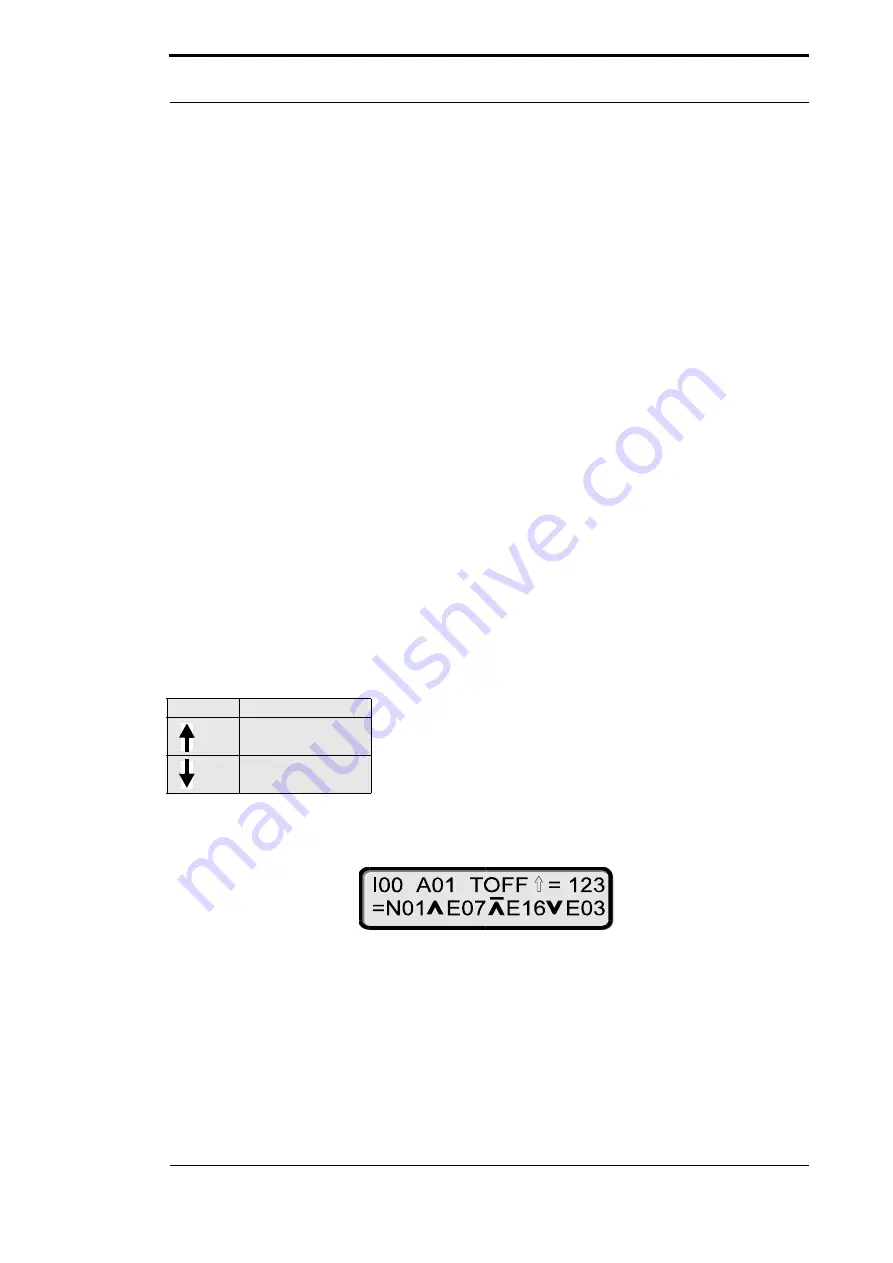
Example 1
An example with 3 inputs and a switch-off delay is given below
In this example, the status of output 1 results as follows:
The programmed cams of track 1 (N01) are first AND-ed with input 7 (E07) and with the negated
input 16 (E16) (NAND). After this, this result is OR-ed with input 3 (E03). This state is then output
at output 1 until the switch-off delay has elapsed (see illustration).
Max. 1.5 ms may elapse after an input change until output of the result. The input pulses must be
at least as long as the cycle time (see Technical Data).


