Displaying the Default Buffer Profile
Displaying Buffer Profile Allocations
Dell Networking OS Behavior
: If you attempt to apply a buffer profile to a non-existent port-pipe, Dell
Networking OS displays the following message. However, the configuration still appears in the running-
config.
%DIFFSERV-2-DSA_BUFF_CARVING_INVALID_PORT_SET: Invalid FP port-set 2 for
linecard 2. Valid range of
port-set is <0-1>
Configuration changes take effect immediately and appear in the running configuration. Because, under
normal conditions, all ports do not require the maximum allocation, the configured dynamic allocations
can exceed the actual amount of available memory; this is called oversubscription. If you choose to
oversubscribe the dynamic allocation, a burst of traffic on one interface might prevent other interfaces
from receiving the configured dynamic allocation, which causes packet loss.
You cannot allocate more than the available memory for the dedicated buffers. If the system determines
that the sum of the configured dedicated buffers allocated to the queues is more than the total available
memory, the configuration is rejected, returning a syslog message similar to the following.
00:04:20: %S50N:0 %DIFFSERV-2-DSA_DEVICE_BUFFER_UNAVAILABLE: Unable to allocate
dedicated buffers for
stack-unit 0, port pipe 0, egress port 25 due to unavailability of cells
Dell Networking OS Behavior
: When you remove a buffer-profile using the
no buffer-profile [fp
| csf]
command from CONFIGURATION mode, the buffer-profile name still appears in the output of
the
show buffer-profile [detail | summary]
command. After a line card reset, the buffer profile
correctly returns to the default values, but the profile name remains. Remove it from the
show buffer-
profile [detail | summary]
command output by entering the
no buffer [fp-uplink |csf]
linecard port-set buffer-policy
command from CONFIGURATION mode and the
no buffer-
policy
command from INTERFACE mode.
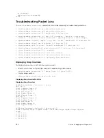
Display the allocations for any buffer profile using the
show
commands, shown in the following
examples. Display the default buffer profile using the
show buffer-profile {summary | detail}
command from EXEC Privilege mode, also shown in the following examples.
Dell#show buffer-profile detail interface gigabitethernet 0/1
Interface Gi 0/1
Buffer-profile -
Dynamic buffer 194.88 (Kilobytes)
Queue# Dedicated Buffer Buffer Packets
(Kilobytes)
0 2.50 256
1 2.50 256
2 2.50 256
3 2.50 256
4 9.38 256
5 9.38 256
6 9.38 256
7 9.38 256
Dell#show running-config interface tengigabitethernet 2/0 !
interface TenGigabitEthernet 2/0
no ip address
mtu 9252
switchport
948
Z-Series Debugging and Diagnostics
Содержание Z9000
Страница 1: ...Dell Configuration Guide for the Z9000 System 9 7 0 0 ...
Страница 80: ...grub reboot 80 Management ...
Страница 128: ... 0 Te 1 1 Te 1 2 rx Flow N A N A 128 Access Control Lists ACLs ...
Страница 436: ...Figure 50 Inspecting Configuration of LAG 10 on ALPHA 436 Link Aggregation Control Protocol LACP ...
Страница 439: ...Figure 52 Inspecting a LAG Port on BRAVO Using the show interface Command Link Aggregation Control Protocol LACP 439 ...
Страница 440: ...Figure 53 Inspecting LAG 10 Using the show interfaces port channel Command 440 Link Aggregation Control Protocol LACP ...
Страница 491: ...Figure 70 Configuring OSPF and BGP for MSDP Multicast Source Discovery Protocol MSDP 491 ...
Страница 492: ...Figure 71 Configuring PIM in Multiple Routing Domains 492 Multicast Source Discovery Protocol MSDP ...
Страница 496: ...Figure 73 MSDP Default Peer Scenario 1 496 Multicast Source Discovery Protocol MSDP ...
Страница 497: ...Figure 74 MSDP Default Peer Scenario 2 Multicast Source Discovery Protocol MSDP 497 ...
Страница 498: ...Figure 75 MSDP Default Peer Scenario 3 498 Multicast Source Discovery Protocol MSDP ...
Страница 760: ...Figure 100 Single and Double Tag TPID Match 760 Service Provider Bridging ...
Страница 761: ...Figure 101 Single and Double Tag First byte TPID Match Service Provider Bridging 761 ...


