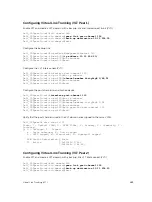
VLT DOMAIN CONFIGURATION mode
peer-link port-channel
id-number
The range is from 1 to 128.
3.
Enter the VLAN ID number of the VLAN where the VLT forwards packets received on the VLTi from
an adjacent peer that is down.
VLT DOMAIN CONFIGURATION mode
peer-down-vlan
vlan interface number
The range is from 1 to 4094.
Configuring Enhanced VLT (eVLT) (Optional)
To configure enhanced VLT (eVLT) between two VLT domains on your network, use the following
procedure.
For a sample configuration, refer to
. To set up the VLT domain, use the
following commands.
1.
Configure the port channel to be used for the VLT interconnect on a VLT switch and enter interface
configuration mode.
CONFIGURATION mode
interface port-channel
id-number
Enter the same port-channel number configured with the
peer-link port-channel
command in
the
Enabling VLT and Creating a VLT Domain
2.
Add one or more port interfaces to the port channel.
INTERFACE PORT-CHANNEL mode
channel-member
interface
interface
: specify one of the following interface types:
• For a 10-Gigabit Ethernet interface, enter the keyword
TenGigabitEthernet
then the slot/port
information.
• For a 40-Gigabit Ethernet interface, enter the keyword
fortyGigE
then the slot/port
information.
3.
Enter VLT-domain configuration mode for a specified VLT domain.
CONFIGURATION mode
vlt domain
domain-id
The range of domain IDs is from 1 to 1000.
4.
Enter the port-channel number that acts as the interconnect trunk.
VLT DOMAIN CONFIGURATION mode
peer-link port-channel
id-number
The range is from 1 to 128.
5.
Configure the IP address of the management interface on the remote VLT peer to be used as the
endpoint of the VLT backup link for sending out-of-band hello messages.
868
Virtual Link Trunking (VLT)
Содержание Z9000
Страница 1: ...Dell Configuration Guide for the Z9000 System 9 7 0 0 ...
Страница 80: ...grub reboot 80 Management ...
Страница 128: ... 0 Te 1 1 Te 1 2 rx Flow N A N A 128 Access Control Lists ACLs ...
Страница 436: ...Figure 50 Inspecting Configuration of LAG 10 on ALPHA 436 Link Aggregation Control Protocol LACP ...
Страница 439: ...Figure 52 Inspecting a LAG Port on BRAVO Using the show interface Command Link Aggregation Control Protocol LACP 439 ...
Страница 440: ...Figure 53 Inspecting LAG 10 Using the show interfaces port channel Command 440 Link Aggregation Control Protocol LACP ...
Страница 491: ...Figure 70 Configuring OSPF and BGP for MSDP Multicast Source Discovery Protocol MSDP 491 ...
Страница 492: ...Figure 71 Configuring PIM in Multiple Routing Domains 492 Multicast Source Discovery Protocol MSDP ...
Страница 496: ...Figure 73 MSDP Default Peer Scenario 1 496 Multicast Source Discovery Protocol MSDP ...
Страница 497: ...Figure 74 MSDP Default Peer Scenario 2 Multicast Source Discovery Protocol MSDP 497 ...
Страница 498: ...Figure 75 MSDP Default Peer Scenario 3 498 Multicast Source Discovery Protocol MSDP ...
Страница 760: ...Figure 100 Single and Double Tag TPID Match 760 Service Provider Bridging ...
Страница 761: ...Figure 101 Single and Double Tag First byte TPID Match Service Provider Bridging 761 ...


