


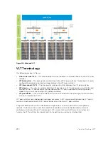


Figure 113. VLT on Switches
VLT on Core Switches
You can also deploy VLT on core switches.
Uplinks from servers to the access layer and from access layer to the aggregation layer are bundled in
LAG groups with end-to-end Layer 2 multipathing. This set up requires “horizontal” stacking at the access
layer and VLT at the aggregation layer such that all the uplinks from servers to access and access to
aggregation are in Active-Active Load Sharing mode. This example provides the highest form of
resiliency, scaling, and load balancing in data center switching networks.
The following example shows stacking at the access, VLT in aggregation, and Layer 3 at the core.
The aggregation layer is mostly in the L2/L3 switching/routing layer. For better resiliency in the
aggregation, Dell Networking recommends running the internal gateway protocol (IGP) on the VLTi VLAN
to synchronize the L3 routing table across the two nodes on a VLT system.
Enhanced VLT
An enhanced VLT (eVLT) configuration creates a port channel between two VLT domains by allowing two
different VLT domains, using different VLT domain ID numbers, connected by a standard link aggregation
control protocol (LACP) LAG to form a loop-free Layer 2 topology in the aggregation layer.
This configuration supports a maximum of four units, increasing the number of available ports and
allowing for dual redundancy of the VLT. The following example shows how the core/aggregation port
density in the Layer 2 topology is increased using eVLT. For inter-VLAN routing and other Layer 3 routing,
you need a separate Layer 3 router.
Virtual Link Trunking (VLT)
849
Содержание Z9000
Страница 1: ...Dell Configuration Guide for the Z9000 System 9 7 0 0 ...
Страница 80: ...grub reboot 80 Management ...
Страница 128: ... 0 Te 1 1 Te 1 2 rx Flow N A N A 128 Access Control Lists ACLs ...
Страница 436: ...Figure 50 Inspecting Configuration of LAG 10 on ALPHA 436 Link Aggregation Control Protocol LACP ...
Страница 439: ...Figure 52 Inspecting a LAG Port on BRAVO Using the show interface Command Link Aggregation Control Protocol LACP 439 ...
Страница 440: ...Figure 53 Inspecting LAG 10 Using the show interfaces port channel Command 440 Link Aggregation Control Protocol LACP ...
Страница 491: ...Figure 70 Configuring OSPF and BGP for MSDP Multicast Source Discovery Protocol MSDP 491 ...
Страница 492: ...Figure 71 Configuring PIM in Multiple Routing Domains 492 Multicast Source Discovery Protocol MSDP ...
Страница 496: ...Figure 73 MSDP Default Peer Scenario 1 496 Multicast Source Discovery Protocol MSDP ...
Страница 497: ...Figure 74 MSDP Default Peer Scenario 2 Multicast Source Discovery Protocol MSDP 497 ...
Страница 498: ...Figure 75 MSDP Default Peer Scenario 3 498 Multicast Source Discovery Protocol MSDP ...
Страница 760: ...Figure 100 Single and Double Tag TPID Match 760 Service Provider Bridging ...
Страница 761: ...Figure 101 Single and Double Tag First byte TPID Match Service Provider Bridging 761 ...


