SCSI logic requires that termination be enabled for the two devices at opposite ends of the SCSI chain and disabled for all devices in between.
Dell recommends that you use terminated cables and that you disable termination on all devices. See the documentation provided with any optional SCSI
device you purchase for information on disabling termination on the device.
General Guidelines
Follow these general guidelines when installing SCSI devices in your computer:
l
Although you install SCSI devices essentially the same way as other devices, their configuration requirements are different. For details on configuring
your particular SCSI subsystem, refer to the documentation for your SCSI devices and/or your host adapter card.
l
Configure the device for a SCSI ID number and disable termination, if necessary.
l
If you are installing an external SCSI device
,
connect one end of the external SCSI cable to the bus connector on the back of the device. Attach the
other end of the external SCSI cable to the connector on the controller installed in the computer.
l
After installing a SCSI hard drive,
Primary Drive 0
and
Primary Drive 1
should be set to
None in
system setup
. If you have any EIDE devices on the
second EIDE channel, such as a CD or tape drive,
Secondary Drive 0
and/or
Secondary Drive 1
should be set to
Auto.
If you have any SCSI devices on
the second EIDE channel,
Secondary Drive 0
and/or
Secondary Drive 1
should be set to
None.
l
You may need to use programs other than those provided with the operating system to partition and format SCSI hard drives. Refer to the
documentation that came with your SCSI software drivers for information on installing the appropriate drivers and preparing your SCSI hard drive for
use.
SCSI Cables
Ultra2/Wide low-voltage differential (LVD) drives (typically hard drives) use a 68-pin cable. One end of this cable attaches to the SCSI controller card. The
remaining connectors on the cable attach to the various LVD drives.
Narrow SCSI drives (tape drives, CD drives, and some hard drives) use a 50-pin cable. One end of this cable attaches to the SCSI controller card. The
remaining connectors on the cable attach to the various Narrow SCSI devices.
AGP Card Brace
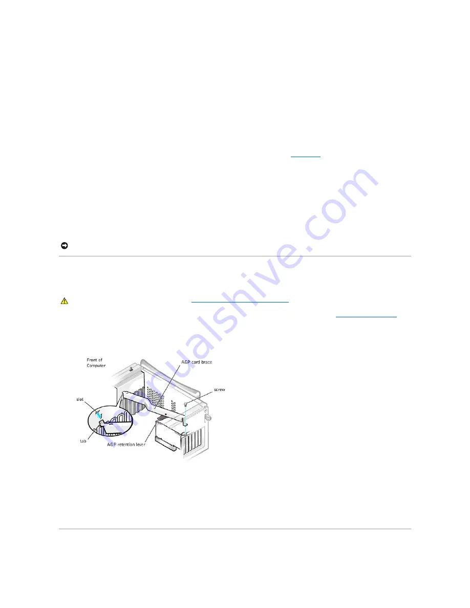
To access some components on the system board in the chassis, you may need to remove the accelerated graphics port (AGP) card brace.
1.
Turn off the computer and peripherals, disconnect them from their electrical outlets, wait at least 5 seconds, and then
remove the computer cover
.
2.
Lay the computer on its right side.
3.
Remove the screw that secures the AGP card brace to the chassis (see the following figure).
Removing the AGP Card Brace
4.
Rotate the brace up until it disengages from the card guide at the front of the chassis. Then lift the brace away from the chassis.
To replace the AGP card brace, perform the following steps:
1.
Insert the tab on one end of the brace into the slot on the card guide at the front of the chassis (see the preceding figure).
2.
Lower the brace, ensuring that the AGP retention lever on the bottom of the brace is aligned with the top of the AGP card.
3.
Replace the screw that secures the brace to the chassis.
Expansion Cards
NOTICE:
Dell recommends that you use only SCSI cables purchased from Dell. Cables purchased elsewhere are not guaranteed to work with Dell
systems.
CAUTION:
Before you perform this procedure, see "
Safety First
—
For You and Your Computer
."
Содержание OptiPlex GX400
Страница 37: ...Back to Contents Page ...
Страница 75: ...BSMI Notice Taiwan Only ...
Страница 88: ......


