


NOTICE
It is not possible to run the motor at maximum or
minimum speed, when manually adjusting the motor
speed due to the need of giving the motor a step in the
speed during auto-tuning.
PID auto-tuning functions by introducing step changes
while operating at a steady state and then monitoring the
feedback. From the feedback response, the required values
for
parameter 20-93 PID Proportional Gain
and
parameter 20-94 PID Integral Time
are calculated.
Parameter 20-95 PID Differentiation Time
is set to value 0
(zero).
Parameter 20-81 PID Normal/ Inverse Control
is
determined during the tuning process.
These calculated values are presented in the LCP and can
be either accepted or rejected. Once accepted, the values
are written to the relevant parameters and auto-tuning
mode is disabled in
parameter 20-79 PID Autotuning
Depending on the system the time required to carry out
auto-tuning could be several minutes.
Before carrying out the PID auto tuning, set the following
parameters according to the load inertia:
•
Parameter 3-41 Ramp 1 Ramp Up Time
•
Parameter 3-42 Ramp 1 Ramp Down Time
or
•
Parameter 3-51 Ramp 2 Ramp Up Time
•
Parameter 3-52 Ramp 2 Ramp Down Time
according to the load inertia before carrying out PID
autotuning. If PID autotuning is carried out with slow ramp
times, the auto-tuned parameters typically results in very
slow control. Before activating PID auto tuning remove
excessive feedback sensor noise using the input filter
(parameter groups
6-** Analog In/Out
,
5-5* Pulse Input
, and
26-** Analog I/O Option MCB 109
, Terminal 53/54 Filter Time
Constant/Pulse Filter Time Constant #29/33) before
activating PID autotuning. To obtain the most accurate
controller parameters, carry out PID autotuning when the
application runs in typical operation, that is with a typical
load.
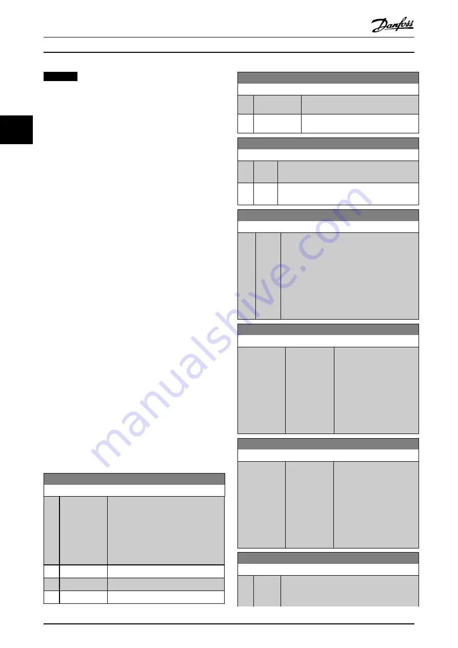
20-70 Closed Loop Type
Option:
Function:
Select the application response speed if it
is known. The default setting is sufficient
for most applications. A more precise
value decreases the time needed for
carrying out PID adaptation. The setting
has no impact on values of parameters
and only affects the auto-tuning speed.
[0]
*
Auto
Takes 30–60 s to complete.
[1]
Fast Pressure
Takes 10–20 s to complete.
[2]
Slow Pressure
Takes 30–60 s to complete.
20-70 Closed Loop Type
Option:
Function:
[3]
Fast
Temperature
Takes 10–20 min to complete.
[4]
Slow
Temperature
Takes 30–60 min to complete.
20-71 PID Performance
Option:
Function:
[0]
*
Normal Normal setting of this parameter is suitable for
pressure control in fan systems.
[1]
Fast
Fast setting is used in pumping systems, where a
faster control response is wanted.
20-72 PID Output Change
Range:
Function:
0.10
*
[0.01 -
0.50 ]
This parameter sets the magnitude of step
change during autotuning. The value is a
percentage of full speed. I.e. if maximum output
frequency in
parameter 4-13 Motor Speed High
parameter 4-14 Motor Speed High Limit
is set to 50 Hz, 0.10 is 10% of 50 Hz, which is
5 Hz. This parameter should be set to a value
resulting in feedback changes of between 10%
and 20% for best tuning accuracy.
20-73 Minimum Feedback Level
Range:
Function:
-999999
ProcessCtrlUnit
*
[ -999999.999 -
par. 20-74
ProcessCtrlUnit]
Enter the minimum allowable
feedback level in user units as
defined in
20-12 Reference/
Feedback Unit
. If the level
drops below
parameter 20-73 Minimum
Feedback Level
, auto tuning is
aborted and an error
message appears in the LCP.
20-74 Maximum Feedback Level
Range:
Function:
999999
ProcessCtrlUnit
*
[ par. 20-73 -
999999.999
ProcessCtrlUnit]
Enter the maximum allowable
feedback level in user units as
defined in
20-12 Reference/
Feedback Unit
. If the level
rises above
parameter 20-74 Maximum
Feedback Level
, auto tuning is
aborted and an error
message appears in the LCP.
20-79 PID Autotuning
Option:
Function:
This parameter starts the PID autotuning
sequence. Once the autotuning has successfully
completed and the settings have been accepted
Parameter Descriptions
VLT
®
HVAC Drive FC 102
148
Danfoss A/S © 03/2015 All rights reserved.
MG11CE02
3
3
Содержание VLT HVAC Drive FC 102
Страница 1: ...Programming Guide VLT HVAC Drive FC 102 vlt drives danfoss com...
Страница 2: ......