background image

Optyma Plus 

TM 

User 

Guide RS8GD602 © Danfoss 2015-10 

5

Data communication

The controller is delivered with built-in MODBUS data 

communication.

If a different form of data communication is requested, a LON RS-

485 module can be inserted in the controller. 

The connection will then be made on terminal RS 485.

Important

All connections to the data communication must comply with the 

requirements for data communication cables. 

See literature: RC8AC. 

Display

The controller has one plug for a display. Here display type EKA 

163B or EKA 164B (max. length 15m) can be connected. 

EKA 163B is a display for readings.

EKA 164B is both for readings and operation.

The connection between display and controller must be with a 

cable which has a plug at both ends.

A setting can be made to determine whether the Tc or Ts is to be 

read out. When the value is read out, the second read-out can be 

displayed by briefly pressing the lower button. 

When a display is to be connected to the built-in MODBUS, the 

display can advantageously be changed to one of the same type, 

but with Index A (version with screw terminals).

The controllers address must be set higher than 0 in order for the 

display to be able to communicate with the controller.

If connection of two displays is required, one must be connected 

to the plug (max. 15 m) and the other must then be connected to 

the fixed data communication. 

Override

The controller contains a functions which can be used together 

with the override function in the master gateway/system man-

ager.   

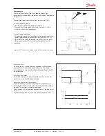
Heating element in the crankcase

The controller has a thermostat function which can control the 

heating element for the crankcase. Oil can thus be kept separate 

from the refrigerant. The function is active when the compressor 

has stopped.

The function is based on the ambient temperature and suction 

gas temperature. When the two temperatures are equal ± a 

temperature difference, power will be supplied to the heating 

element.

The 'CCH off diff' setting indicates when power will no longer be 

supplied to the heating element.

The 'CCH on diff' indicates when 100% power will be sent to the 

heating element.

Between the two settings the controller calculates the wattage 

and connects to the heating element in a pulse/pause cycle which 

corresponds to the desired wattage.

The Taux sensor can be used to record the temperature in the 

crankcase if desired. 

When the Taux sensor records a temperature lower than Ts+10 K, 

the heating element will be set to 100%, but only if the ambient 

temperature is below 0°C.

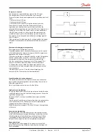
Digital inputs

There are two digital inputs DI1 and DI2 with contact function and 

one digital input DI3 with high voltage signal. 

They can be used for the following functions:

DI1: Starts and stops compressor

DI2: Here the user can select from various functions

Status notification from an external safety function

External main switch

Night setback signal

Separate alarm function

Monitoring of input signal

DI3: Safety signal from low/high-pressure switch

Function via data communication

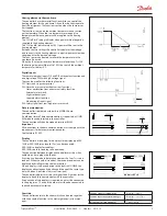
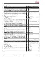
Day/Night schedule

Function in gateway/system manager

Day/Night control / Time 

schedule

Used parameters in OptymaPlus

--- Night setback

Address o03 > 0

Содержание Optyma Plus

Страница 1: ...Controller for Condensing unit Optyma Plus TM User Guide...

Страница 2: ...value The controller can also control the heating element in the crank case so that oil is kept separate from the refrigerant For excess discharge temperature the liquid injection will be acti vated i...

Страница 3: ...terminal 15 16 will be active when the fan is in operation In menu F17 the user can define which of the two controls to use Jog Min Jog low Jog Speed Speed Required capacity Fan speed at start When th...

Страница 4: ...set delay time the compressor will be stopped The compressor will only be re started once the temperature is 10 K lower than the set value The above mentioned re start restrictions must also be compl...

Страница 5: ...in the master gateway system man ager Heating element in the crankcase The controller has a thermostat function which can control the heating element for the crankcase Oil can thus be kept separate fr...

Страница 6: ...d for the suction pressure Ts in degrees r23 Ts Ref Reference Tc Here the current controller reference for condensing pressure Tc can be read out in degrees r29 Tc Ref Minimum condensing temperature l...

Страница 7: ...the temperature is still too high An alarm will also be issued c72 Disch Del Max pressure Max condensing pressure The maximum permitted condensing pressure is set here If the pressure increases the co...

Страница 8: ...an be limited here The value can be entered by setting the nominal speed of 100 to the desired percentage F19 MaxFanSpeed Manual fan speed control An override of the fan speed control can be performed...

Страница 9: ...type of condensing unit Factory set After the first setting the value is locked and can only be changed once the control ler has been reset to its factory setting When entering the refrigerant settin...

Страница 10: ...e The time the compressor must operate at Boost speed P80 ORM BoostTim Service Service Read pressure Pc u01 Pc bar Read temperature Taux u03 T_aux Status on DI1 input On 1 closed u10 DI1 status Status...

Страница 11: ...us codes have the following meanings Ctrl state Normal regulation S0 0 When the compressor is operating it must run for at least x minutes S2 2 When the compressor is stopped it must remain stopped fo...

Страница 12: ...Set o30 A16 DI2 alarm DI2 alarm Check the function that sends a signal at the DI2 input A17 HP Alarm C73 DI3 Alarm High low pressure alarm See instructions for the condensing unit A45 Standby mode Sta...

Страница 13: ...eady be set to 0 which means stopped regulation 2 Select refrigerant via parameter o30 3 Open parameter r12 and start the regulation Start stop at input DI1 or DI2 must also be activated 4 Go through...

Страница 14: ...ion c83 30 s 360 s 60 s Liquid Injection Offset c88 0 1 K 20 0 K 5 0 K Liquid Injection hysterese c89 10 0 K 30 0 K 15 0 K Compressor stop delay after Liquid injection c90 0 s 10 s 3 s Desired compres...

Страница 15: ...h Read out of compressor operating time Value must be multiplied by 1 000 The value can be adjusted P49 0 h Read out of operating time of heating element in crankcase Value must be multiplied by 1 00...

Страница 16: ...ust then be carried out by one of the other methods Supply voltage 230 V a c This must be the same phase for all 230 V connections FAN Fan connection Speed controlled internally Alarm There is a conne...

Страница 17: ...Min 28 V a c Max 2 0 A Leak 1 mA Relays CE 250 V a c Comp CCH 4 3 A Alarm Fan Aux 4 3 A Analog output 2 pcs 0 10 V d c For external speed control of fans and compressors Min load 10 K ohm Max 1 mA Env...

Страница 18: ...s logotype are trademarks of Danfoss A S All rights reserved Ordering Type Function Code no Optyma PlusTM Condensing unit controller Prepared for data communication Plug for screw terminals not enclos...

Отзывы: