8
User
Guide RS8GD602 © Danfoss 2015-10
Optyma
Plus
TM
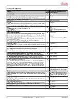
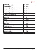
Integration Time Tn
If the Tn value is increased, the fan speed will change.
n05
Tn sec
Amplification factor Kp max
The regulation uses this Kp, when the measured value is far from reference
n95
Cmp kp Max
Fan speed
The actual fan speed is read out here as a % of nominal speed.
F07
Fan Speed %
Change in fan speed
A permitted change in fan speed can be entered for when the fan speed is to be low-
ered. The setting can be entered as a percentage value per second.
F14
DownSlope
Jog speed
Set the fan's start-up speed here. After ten seconds the function jog function will stop
and the fan speed will then be controlled by the normal regulation.
F15
Jog Speed
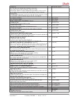
Jog speed at low temperatures
Enter the desired jog speed for outside temperatures of -20°C and lower here.
(For outside temperatures b10 and -20, the controller will calculate and
utilise a speed between the two jog settings.)
F16
LowTempJog
Fan control definition
0: Off
1: The fan is connected to terminal 5-6 and is speed-controlled by an internal phase
cut. The relay on terminal 15-16 connects at speed requirements of 95% or higher.
2: The fan is connected to an external speed control device. The speed control signal
is connected to terminals 28-29. The relay on terminal 15-16 will connect when
regulation is required. (During external control, the settings F14, F15 and F16 will
remain in force)
F17
FanCtrlMode
Minimum fan speed
Set the lowest permitted fan speed here. The fan will be stopped if the user enters a
lower speed.
F18
MinFanSpeed
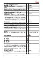
Maximum fan speed
The fan's top speed can be limited here. The value can be entered by setting the
nominal speed of 100% to the desired percentage.
F19
MaxFanSpeed
Manual fan speed control
An override of the fan speed control can be performed here. This function is only
relevant when the main switch is in service mode.
F20
Manual Fan %
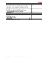
The LED on the controller’s front will show whether Fan is in progress supplied either
through fan speed control output or fan relay.
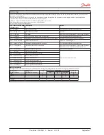
Real time clock
When using data communication the clock is automatically adjusted by the system
unit. If the controller is without data communication, the clock will have a power
reserve of four hours.
(Times cannot be set via data com-
munication. Settings are only relevant
when there is no data communica-
tion).
Switch to day operation
Enter the time at which the control reference becomes the entered set point.
t17
Day start
Change to night operation
Enter the time at which the control reference is raised with r13.
t18
Night start
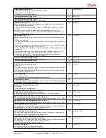
Clock: Hour setting
t07
Clock: Minute setting
t08
Clock: Date setting
t45
Clock: Month setting
t46
Clock: Year setting
t47
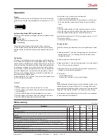
Miscellaneous
Miscellaneous
If the controller is built into a network with data communication, it must have an ad-
dress, and the system unit of the data communication must then know this address.
The address is set between 0 and 240, depending on the system unit and the selected
data communication.
o03
The function is not used when the data communication is MODBUS. It is retrieved
here via the system's scan function.
o04
Access code 1 (Access to all settings)
If the settings in the controller are to be protected with an access code you can set a
numerical value between 0 and 100. If not, you can cancel the function with setting 0.
(99 will always give you access).
o05
Acc. code
Controller software version
o08
SW ver


