Installation Manual
EDUS72-975
36
BRC1E71
3P243521-2B
6
English
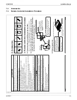
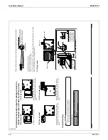
Prepare the cabling for connection to the remote controller following these instructions:
Remove the cable jacket
and insulation
Cutting guideline
Approx. 3/8 inch
T
o
simplify the wiring, maintain
a 3/8in dif
ference between the
length of the two conductors.
Length of jacket to be removed:
Approx. 6 inch for top left outlet
Ɣ
Approx. 8 inch for top center outlet
Ɣ
Connect the terminals (P/P1, N/P2) of the remote controller to the terminals (P1, P2) of the
indoor unit. (P1 and P2 are not polarity sensitive.)
Back outlet
3-5-1
<Cable attachment guideline>
Lower case
P1
Indoor unit
P2
Upper case
PC-board
Clamp
Cable attachment
point
Cross-section
-
Secure the cable at
the attachment point
by using furnished
clamping material.
Clamp
01_EN_3P243521-2B.indd 6
8/27/2009 2:00:09 PM
English
5
Determine the location where the cabling will enter the
3-4
remote controller (back, left side, top left, top center).
Back outlet
3-4-1 Left
outlet
3-4-2
Cut of
f resin area (hatched area).
Using an appropriate tool, cut the plastic at
the hatched area and remove any remaining
burrs.
T
op left outlet
3-4-3
T
op center outlet
3-4-4
Using an appropriate tool, cut the plastic at
the hatched area and remove any remaining
burrs.
Using an appropriate tool, cut the plastic at
the hatched area and remove any remaining
burrs.
Install wiring.
3-5
1.
Switch box and control wiring are not attached.
Do not touch the remote controller PC-board.
2.
NOTE
Wiring Specifi
cations
Wiring
T
ype
Non-shielded, 2-conductor
, stranded copper cable
Wiring Size
A
W
G-18
Wiring Length
Maximum 1640 feet (500m)
01_EN_3P243521-2B.indd 5
8/27/2009 2:00:08 PM
Содержание BRC1E71
Страница 1: ...AMERICAS...
Страница 8: ...EDUS72 975 Features BRC1E71 7 1 5 Other Features...

